Case Studies
Vision system automatically inspects automotive electronics assemblies
Automated Optical Inspection (AOI) systems are used in the production of printed circuit boards (PCBs) for the electronics industry. In the manufacturing of products such as smart phones, consumer products and computers, such fully automated AOI systems check component defects, their correct component placement and their length, width and height at high-speed. Needless to say, such systems are expensive since they incorporate disparate imaging technologies to perform these tasks.
In many electronics manufacturing processes, however, especially those where small batches of products are produced, semi-automated systems can be employed. In such systems, an operator is required to place the part in a fixture, position it and initiate the inspection process. Although slower than fully automated inspection systems, semi-automated systems are more cost effective since they may not require developers to incorporate conveyors, or three-dimensional (3D) component analysis demanded by fully automated AOI systems for high-speed PCB inspection.
Electronic assembly inspection
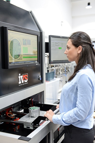
Industrial Vision Systems (www.industrialvision.co.uk), manufacture manual AOI systems for the inspection of electronic assemblies and PCBs. As a stand-alone unit, the system checks for correct PCB component placement, component defects, whether the unit is correctly housed and whether it has been correctly sealed. A video of a system in operation can be viewed at: .
The unit being inspected, an electronic sub-assembly for the automotive industry, consists of a base aluminium housing, and a PCB mounted at the top of the housing. In operation, the system verifies the positions of the electronic and electrical components on the PCB, whether the PCB is correctly positioned and reads a 2D matrix tracking code on the side of the aluminium housing. After this process is complete, the unit is removed from the inspection system and a cap is then placed on the top of the unit. After being re-inserted into the inspection system, the shape of the cap and its orientation are verified. Since the operator must remove the part to insert this cap, it is also necessary to again perform 2D matrix bar-code reading to ensure that the part being inspected is the same as the one previously inspected for PCB component placement. In this way, any operator error is eliminated.
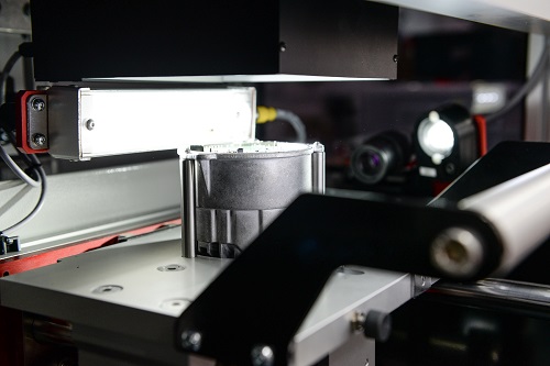
To perform these tasks, the electrical housing is first placed into a custom built nest after which it is positioned into the machine vision system. In the design of the system, two cameras are placed at on and off-axis locations to view the part. The on-axis camera, an IVS color USB3 camera is used to image the PCB.
To ensure that the components on the PCB are imaged accurately and repeatably and that any blurred edges that may be caused by diffuse reflections are eliminated, the camera is coupled to a bi-telecentric lens via a C-mount thread to provide a 160 x 120 mm field of view (FOV) of the PCB. A custom 90º diffuse axial light mounted in front of the lens provides the diffuse light illumination needed to improve image consistency while avoiding any reflections and shadowing effects that may occur otherwise.
Data matrix code
Before the on-axis camera is used to check whether components are correctly in place, however, the system must first validate whether the 2D Data Matrix code on both the PCB and the side of the unit’s housing are correct. To do so, a second camera, an IVS USB color camera is positioned at 90 to the part.
To read both the Data Matrix code on the PCB and the unit’s housing, images captured by both cameras are transferred to an industrial PC over a USB3 interface using the IVS software. After images are captured, both ECC 200 Data Matrix codes are read by the IVS software. After reading, barcode data is transferred over an industrial Ethernet interface to the automotive manufacturer’s factory information system that is then used to initiate the final testing procedure.
Since the electrical components on the PCB have already been tested electrically and whether the solder joints are acceptable, the final inspection process requires a check of whether components have been correctly placed and not damaged. Thus, at the next stage of the inspection process, components on the PCB must be validated as being correctly placed and that the PCB is properly fitted into its aluminium housing. To do so, requires first defining over 170 regions of interest (ROIs) within the field of view of the image using a known good part. These ROIs are then used to perform pattern matching on any new part being imaged.
The vision system’s human machine interface (HMI) developed by IVS provides an analysis of the PCB inspected showing failed areas highlighted in red. This provides feedback to the operator of missing and/or damaged components.
Proper placement
As well as ensuring proper component placement, the system must also determine whether the PCB is positioned correctly in the aluminium housing. This positioning is achieved using three protruding plastic pins located at both the sides and bottom of the PCB. Since the pins are used to secure the PCB in the housing, their presence must be ensured before a plastic cap is placed onto the unit. To accomplish this task, a 3D profiling system could have been used to perform this task.
However, since such systems are relatively expensive, a rather elegant less-costly solution was employed. Realizing that that the protruding pins would cast a shadow when illuminated from an angle, the system employs a 150mm long white bar light from Spectrum Illumination mounted at a 90o angle to the PCB. Thus, by illuminating the board from the top and sides simultaneously, the shadows cast by the protruding pins can be used to determine pin presence and height, to confirm they have not been damaged.
After performing Data Matrix reading proper component placing and fixturing, the automotive assembly must be capped. To perform this task, the unit is removed by the operator and a plastic cap placed onto the top. After placement, the operator then re-inserts the assembly into the inspection system. Data Matrix code on the side of the part is then again inspected to ensure that the part checked for proper component and placement is the same.
To perform the task of cap inspection, the unit is illuminated from above and template matching software again used to verify both its shape and orientation. After this process is complete, the validated part and image data is transferred and logged to the automotive company’s factory automation system, allowing image archiving against Data Matrix serial numbers so that the manufacturer can track any later warranty claims. Validated parts are then shipped to the customer for final assembly.