Case Studies
Automated inspection of Axial Piston Motors
Earth moving machines require an immense energy source to provide the power they need for use within civil engineering works. ‘Hydraulic Motors’ allow this power to be applied to enable the machines movement and in addition ‘Control Valves’ also provide the operator with the precise feel and control required to undertake the necessary tasks needed for such machines, including trenching, rock breaking and demolition. These same motors are also used in cranes, wheel loaders and general construction equipment.
Though not a new product, the designs of such motors and control valves have been around a few decades, the overall method for manufacture has changed rapidly over the last few years to take account of the need for more modular designs, manufacture and just-in-time manufacturing. Kawasaki Precision Machinery (UK) Ltd based in Plymouth, UK is one of the leading manufacturers of such motors and pumps. They approached Industrial Vision Systems Ltd to come up with a solution to provide automated inspection of such pumps for their semi-automated assembly process.
The pumps requiring inspection are at asub-assembly stage when they are due for the inspection process totake place. Due to the highly modular nature of the construction each partof the pump can have many different derivatives which overall have a differenteffect on the pump in industrial use. It is therefore critical for the manufacturingprocess to check all components arethe correct type and number for the construction of the pump to begin. Once built it is difficult and costly to rework such units if a fault is detected later in the manufacturing process, therefore automated visual inspection is critical for the success in building quality motors and pumps.
System Architecture
The first ideas for the system architecture related to the vision system positioning relative to the parts requiring inspection. For manual inspection processes the precise positioning or presentation of the products is not so relevant, an operator inspecting a product can pick it up and turn it around to view all sides. On the other hand the vision system requires each component to be presented repeatedly in the same position across all variants in order to accurately inspect it and the lighting must also be repeatable and fixed.
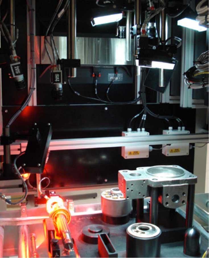
On this basis the first part of the project involved systematically defining how each part could be presented on a fixture to the vision system, ideally fitting all components onto one large fixture design in order for multiple cameras to view all components in one inspection position. These parts included the Pump Case, Shaft, Cylinder Block, Valve Plate and Valve Cover. This design had a number of challenges relating to the large number of variant sizes which had to be accommodated along with making sure each component was easily seen when all parts and variations were present. Lighting techniques are also critical for automated vision systems and so it was also necessary to confirm the lighting for each position and camera relative to each other.
Once the final design for the travel board fixture was defined the final camera position and lighting position could be confirmed. The final system design involved 6 off digital Gigabit Ethernet cameras connected to a central Industrial PC unit running the IVS Vision software.

Cycle time for the inspection process is not critical as the manufacture of such pumps is on a relatively slow cycle, only one part every few minutes is required to be inspected.
It was intended that the travel board fixture would be pushed into the inspection station on a roller conveyor, with the fixture locked in place during the inspection process. The vision system would not release the fixture to continue down the production line if a failure was identified; instead the fixture was to be pulled back to the entry operator to rework the fixture board in case of failure.

System Design
Built from an extruded aluminiumframework, the machine incorporates a central roller feed conveyor systemand incorporated into the conveyor are pneumatically-driven stops. The cameras, optics and lights are mounted from individual doweled fixtures mountedinside the main inspection canopy. The whole system was shielded from ambient lighting to stop this affecting the vision system result.
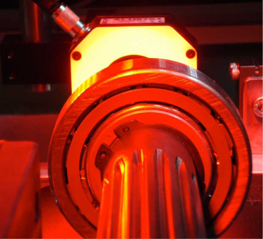
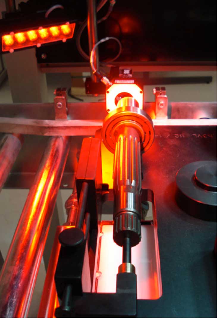
The lighting used was a combination of high intensity white LED area light units with built in polarisers, combined with red LED ring lights units for specific inspection tasks (e.g. inspection of the shaft end). The fixture carrier was manufactured from black anodised aluminium with a matt finish to offer a contrast in placement on some of the components. Optics were specified to give the correct field of view and positioning for the cameras.
Imaging Algorithms
Machine vision inspection functions were then selected from standard routines available and deployed to check the six main components on the fixture board in sequence. The main shaft inspection application was designed to check the number and type of teeth on the shaft to confirm it was the correct type. This utilised a rotating template matching facility to allow templates to be found within the defined regions of interest irrespective of their rotational position. The teeth were then counted and mapped based on their size and type; this ultimately allowed the IVS system to confirm the shaft matched that requested by the line PLC system.
The complete manifest information was transferred from the master PLC to the machine PLC via Ethernet, this was then used to open the relevant inspection routines within the software to confirm the parts match the manifest.

Pump Inspection
The main pump inspection and the associated valve plate and cover checks were completed via the use of a match against a trained template of the relevant type. Due to the precise positioning of the products on the board no rotational movement of the templates was required.
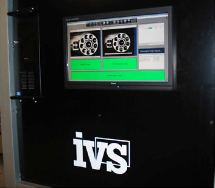
After the software has examined all the characteristics of all the components, it then determines whether the pump manifest meets all the tolerances that have been specified, or whether the parts must be reworked or rejected.
Statistical Data
Whilst the data from the image processing system can be used to efficiently inspect and categorise the devices and only allow good products to continue down the production line, it has other benefits. The vision system is able to collect statistical data during the inspection process, after the machine has checked several batches of product; the data can be used to determine how any changes in acceptable tolerances will affect the yield of the product. In addition the system provides ongoing statistical process control for the products being manufactured for later analysis. Images of every product can also be saved and allocated against serial number tracking to allow photos of every product leaving the factory to be stored if required.

Conclusion
The vision system provides a method for the 100% inspection of the pump product prior to assembly of the complete unit for Kawasaki Precision Machinery therefore allowing a more modular approach to production to be adopted and a great degree of flexibility to be offered to their customers in the future with regard to the modular designs and functionality offered. Ultimately it provides their customers with the reassurance that the product is being built to the required specification and that the quality offered by Kawasaki is of the highest level possible.

