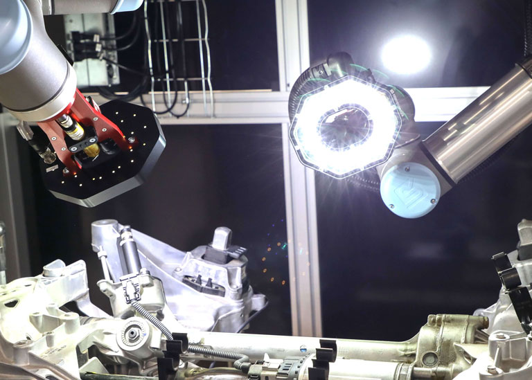
This month, we are discussing one of the main, and sometimes underutilised, elements of vision systems – lighting. Lighting in machine vision quality control is perhaps one of the most important aspects to get right. It’s critical because it enables the camera to see necessary details. In fact, poor lighting is one of the major causes of failure of machine vision system installations and poor yield performance of a vision system. Therefore, it should be a top priority in determining the correct lighting approach for a machine vision application. While the latest generation AI deep learning vision systems can compensate to some extent for fluctuations in lighting, nothing will replace the ability to light a product accurately to allow defective areas to be seen by the camera. Getting these fundamentals right makes the job of the software image processing much more manageable.
For every vision quality control application, there are common lighting goals:
- Maximising feature contrast of the part or object to be inspected.
- Minimising contrast on features not of interest.
- Removing distractions and variations to achieve consistency.
In this respect, the positioning and type of lighting are key to maximising the contrast of inspected features and minimising everything else. Think of how a manual operator would inspect a part for quality. Typically, they would turn it in front of the light while moving their head to see how the light reflects off of specific areas, slowly covering the whole part or necessary detail as required. Sometimes, even holding it up to the light to create a background to see contamination or features. A human does all this instinctively, but for a digital vision system, this somehow has to be replicated – and at high speed!
Lighting position
The first thing to consider is the lighting position. The position of the lighting will determine the brightness, shadowing, contrast, and what element of light will be seen by the camera system. The overall classification of machine vision lighting positions can be seen below.
| Description | Characteristics | Features |
|---|---|---|
| Front illumination – the light is positioned on the same side as the camera/optics | Useful for inspecting defects or features on the surface of an object | 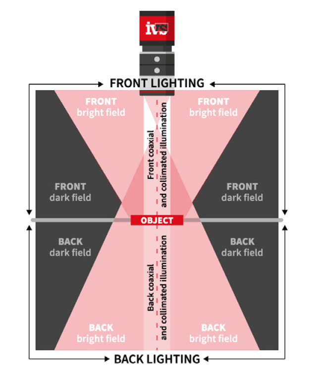 |
| Back illumination – the object being illuminated blocks light on its way to the camera | Useful for highlighting the object silhouette, measuring outline shape and detecting presence/absence of holes or gaps, as well as enhancing defects on transparent objects |
Types of machine vision lighting
Within machine vision, the two most common types of lighting used are fibre optics and LED. Fibre optics allows the lighting source to be positioned away from the scene, with a fibre optic cable delivering the light to the vision system scene. This can also allow a higher lux light level to be concentrated into a smaller area.
| Fibre Optic | Deliver light from halogen, tungsten‐halogen or xenon source. Bright, shapeable & focused. | 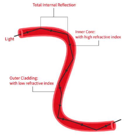 |
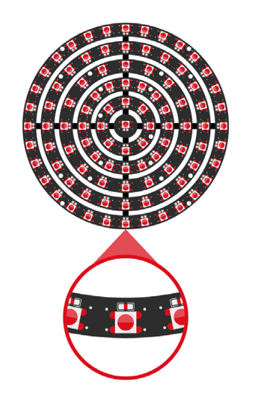
| LED lights | By far the most commonly used because:
|
 |
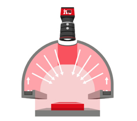
| Dome lights |
|
 |
| Telecentric lighting |
|
|
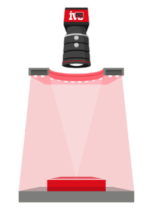
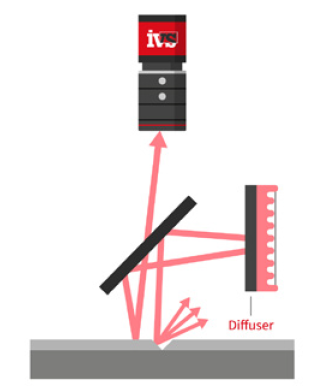
| Diffused light |
|
|
| Direct light |
|
 |
Other key elements to consider when designing lighting for a machine vision environment include the direction, brightness and colour/wavelength compared to the target’s colour.
Lighting angle/direction
The position and angle of the LEDs have a direct effect on the ability of the vision system camera to see contrast in certain areas. This allows lighting setups to be designed to provide the optimum lighting conditions to highlight key areas of the product. This makes the image processing of the machine vision system image more consistent and makes it easier to provide a robust solution. There are several different techniques to think about in this area.
| Bright field – Light reflected by the object being illuminated is inside of the optics/camera range | Brightfield front lighting – Light reflected by the flat object being illuminated is collected by the optics/camera. Produces dark characteristics on a bright background | 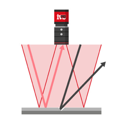 |
| Brightfield back lighting – light is either stopped or if the material is transparent or opaque it will be transmitted through the surface | 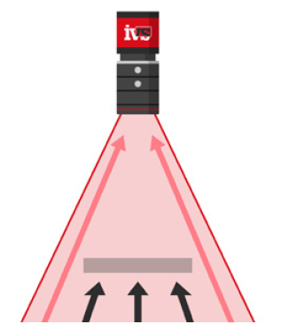 |
|
| Dark field – Light reflected by the object being illuminated is outside of the optics/camera range | Dark field front lighting – reflected light is not collected by the optics/camera. Enhances the non-planar features of the surface as brighter characteristics on a dark background | 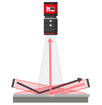 |
| Dark field backlighting – light transmitted by the object and scattered by non-flat features will be enhanced as bright on a dark background | 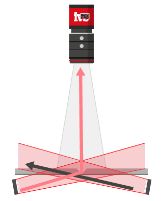 |
|
| Co-axial illumination – The front light is positioned to hit the object surface at 90° | Can additionally be collimated so that rays are parallel to the optics/camera axis and is useful for achieving high levels of contrast when searching for defects on highly reflective surfaces |
 |
Colour/wavelength
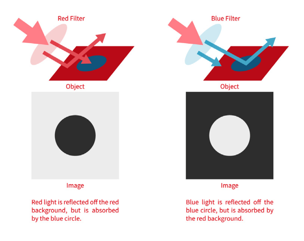
Another aspect to think about when designing machine vision lighting is the filters which can be deployed on the front of the lens. These typically screw onto the front of the lens. They can limit the transmission of specific wavelengths of light, allowing the image to be changed to suit a particular condition that is being identified in the machine vision process.
| Filters |
|
 |
Of course, the parameters outlined in the preceding tables are used in varying combinations and are key to achieving the optimal lighting solution. However, we also need to consider the immediate inspection environment. In this respect, the choice of effective lighting solutions can be compromised by access to the part or object to be inspected. Ambient lighting such as factory lights or sunlight can also have a significant impact on the quality and reliability of inspection and must be factored into the ultimate solution.
Finally, the interaction between the lighting and the object to be inspected must be considered. The object’s shape, composition, geometry, reflectivity, topography and colour will all help determine how light is reflected to the camera and the subsequent impact on image acquisition, processing, and measurement.
Due to the obvious complexities, there is often no substitute other than to test various techniques and solutions. It is imperative to get the best lighting solution in place before starting the development of the image processing requirements in any machine vision quality control application.