Machine vision: The key to safer, smarter medical devices

In this month’s blog, we are discussing the highly regulated field of medical device manufacturing, where precision and compliance are not just desirable—they are mandatory. The growth of the medical devices industry means there have been substantial advances in the manufacturing of more complex devices. The complexity of these products demands high-end technology to ensure each product is of the correct quality for human use, so what’s the key to producing safer, smarter medical devices? Machine vision is one of the most important technologies that allow for the achievement of precision and compliance within the required regulations. In this article, we will touch on the aspect of machine vision in medical device manufacturing and its role in ensuring precision while serving regulatory compliance.

How Machine Vision Works in Manufacturing

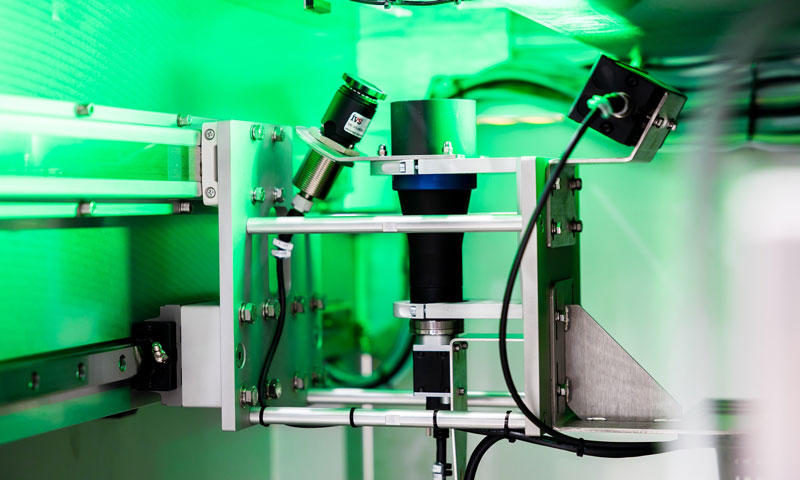
Machine vision (often referred to in a factory context as industrial vision or vision systems) uses imaging techniques and software implementation to perform visual inspections on the manufacturing line for many applications where quality control inspection is required at speed. Using cameras, sensors, and complex algorithms—Visual Perception allows machines to develop a sense of sight by capturing images with the camera(s) and processing them in order to enable decision-making from visual data.

When it comes to the medical device manufacturing process, machine vision systems play a vital role in ensuring the highest levels of precision and quality. Examples include systems that can detect the smallest imperfections, measure components with sub-micron precision, and confirm every product is produced to the tightest of tolerances—all automatically.

The Significance of Medical Device Manufacturing Accuracy

Surgical instruments, injectable insulin pens, contact lenses, asthma devices and medical syringes all need high-precision manufacturing, and this is due to several reasons. The devices not only involve patient health and safety but also must be produced at a legal level, to validated specifications. Even tiny damage or a slight deviation from those specifications can lead to the collapse of these products and hence impact human life. The drive towards miniaturisation in medical devices means that more precise parts have to be manufactured than ever before. With devices getting smaller (miniaturisation) and more complex, the margin for error decreases, hence making precision even more critical.

Machine vision systems can easily maintain precision at these levels due to the precise resolution they run at. The vision systems can use advanced imaging techniques, such as 3D vision, to measure dimensions, check alignments, and verify components are manufactured within tolerance. It makes a quality-assurance check on every unit as it comes off the assembly line to prevent defects and recalls later down the line.

Meeting Compliance Regulations

The medical device industry is heavily regulated by organizations like the FDA (Food and Drug Administration) in the United States, European Medicines Agency (EMA), and other national and international bodies that set relevant standards. Regulations govern every dimension of device manufacture, from design and production to testing and distribution.

The Current Good Manufacturing Practice (CGMP) regulations issued by the FDA draw attention to quality requirements needed throughout the manufacturing process. Machine vision systems can automatically inspect components and end products according to specifications, allowing manufacturers to validate to the relevant regulations.

Machine vision systems can produce extremely stringent inspection records with the traceability required to prove compliance against established regulatory standards. This is crucial specifically for audit purposes; if needed, manufacturers must be able to show evidence that their product was manufactured according to regulations.

Using Machine Vision in the Medical Devices Production

Each of these stages using Machine Vision to ensure precision-orientation compliance with the final product. A few of the main uses are:
Surface Inspection: Vision systems can detect scratches, cracks, and foreign material present on the surface during the manufacturing process, which may lead to a device failure in operation.
Dimensional Measurement: Vision metrology is used for measuring component dimensions to ensure they meet design specifications.
Assembly Verification: Machine vision ensures that components are assembled correctly, reducing defect risk from the assembly process.
Label Verification: Understanding which label goes on which batch is essential for compliance. Machine vision systems can inspect that labels are properly positioned and the writing on them is accurate.
Packaging Inspection: Proper packaging ensures that devices remain sterile and protected while in transit. Machine vision systems ensure that packaging is not defective and is properly sealed.
Code Reading: Machine vision systems check and verify datamatrix & barcodes on products and packaging to maintain correct product identification throughout the supply chain.

Optimising Efficiency and Lowering Costs

The machine vision system has more benefits and is likely to improve manufacturing not only in a precise manner but also with strict compliance while increasing the efficiency of manufacturing, resulting in reduced costs. This will help speed up the throughput from these systems, where automated inspection and measurement can be done much faster and more consistently than a team of human inspectors.

Machine vision products also reduce human error, which could cost in relation to medical device manufacturing. Where a simple mistake can cause the manufacturer to recall defective products, leading them to legal lawsuits and damaging their reputation. Catching defects early can help to minimise these risks and costs, which is why machine vision offers such a huge benefit.

Manufacturers can also use inspection data to analyse trends and uncover underlying issues before they lead to defects, allowing for higher uptime with preventative maintenance of the lines.

Future Trends in Medical Device Manufacturing and Machine Vision

As technology advances, the function of machine vision systems will continue to develop in medical device manufacturing. Here are some of the likely trends we can expect to see over time.
Integration of Artificial Intelligence (AI) with Machine Vision Systems: AI and machine learning are increasingly incorporated into machine vision systems, further advancing image analysis and pattern recognition. This will enable even greater precision and the possibility of detecting less visible imperfections that conventional vision systems might overlook.
3D Vision: Where 2D vision systems are traditionally used, the third dimension is being used more. Due to cross-verification, 3D vision systems provide a complete view of the components (compared to a single-plane 2D view), offering better measurement and inspection capabilities over complex shapes and assemblies.
High-Speed Vision Systems: The push for higher-speed vision systems goes hand in hand with the increased manufacturing speeds being implemented today, and the higher speeds of machines increase demand for accurate inspection.
Edge Computing: With the advent of edge computing, machine vision systems can process data locally with greater power and accuracy to eliminate latency for real-time decisions. This is crucial in applications that need instant feedback to change the manufacturing process.

Conclusion

Medical device manufacturing can be significantly enhanced with the incorporation of machine vision that provides superior levels of precision and compliance. For manufacturers, it also ensures compliance with rigorous regulatory needs by automating inspections and measurements with machine vision systems. While still advancing, the necessity of machine vision in this industry is only likely to become more critical as time goes on and improvements are made in efficiency, accuracy, and overall manufacturing quality.

The magic behind machine vision: Clever use of optics and mirrors

Sometimes, we’re tasked with some of the most complex machine vision and automated inspection tasks. In addition to our standard off-the-shelf solutions in the medical device, pharmaceutical, and automotive markets, we often get involved with the development of new applications for machine vision inspection. Usually, this consists of adapting our standard solutions to a client’s specific application requirement. A standard machine vision camera or system cannot be applied due to either the complexity of the inspection requirements, the mechanical handling, part surface condition, cycle time needs or simply the limitation to how the part can be presented to the vision system. Something new is needed.

This complex issue is often discussed in customer and engineering meetings, and the IVS engineering team often has to think outside the box and perhaps use some “magic”! This is when the optics (machine vision lenses) need to be used in a unique way to achieve the desired result. This can be done in several ways, typically combining optical components, mirrors, and lighting.

So what optics and lenses are used in machine vision?
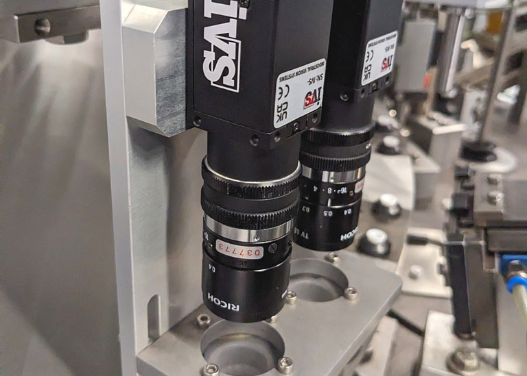
The primary function of any lens is to collect light scattered by an object and reproduce a picture of the object on a light-sensitive ‘sensor’ (often CCD or CMOS-based); this is the machine vision camera head. The image captured is then used for high-speed industrial image processing. When selecting optics, several parameters must be considered, including the area to be imaged (field of view), the thickness of the object or features of interest (depth of field), the lens-to-object distance (working distance), the intensity of light, the optics type (e.g. telecentric), and so on.

Therefore, the following fundamental parameters must be evaluated in optics.
Field of View (FoV) is the entire area the lens can see and image on the camera sensor.
Working distance (WD) is the distance between the object and the lens at which the image is in the sharpest focus.
Depth of Field (DoF) is the maximum range over which an object seems to be in acceptable focus.
In addition, the vision system magnification (ratio of sensor size to field-of-view) and resolution (the shortest distance between two points that can still be distinguished as separate points) must also be appraised.

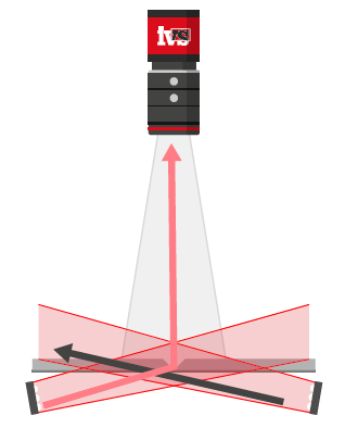
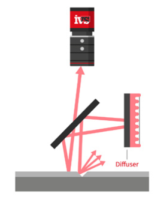
But what if the direct line of the site cannot be seen due to a limitation in the presentation or space available? This is when the magic happens. Optical path planning is used to understand the camera position (or cameras) relative to the part and angle of view required. Combining a set of mirrors in the line of site makes it possible to see over a longer working distance than possible without. The same parameters apply (FoV, WD, DoF etc), but a long optical path can be folded with mirrors to fit into a more compact space. This optical path can be folded multiple times using several mirrors to provide one continuous view through a long path. Cameras can also be mounted closely with several mirrored views to offer a 360-degree view of the product. This is especially true in smaller product inspections like pill or tablet vision inspection checks. Multiple mirrors allow all sides and angles of the pill to be seen, providing a comprehensive automated inspection for surface defects and imperfections for such applications. This technique is also applied in the subtle art of needle tip inspection (in medical syringes) using vision systems, with mirror systems to allow for a complete view of the tip from all angles, sometimes providing a single image with two views of the same product. The optical paths, the effect of specific machine vision lighting and the mechanical design must all be considered to create the most robust solution.

So when our engineers say they will be using “magic” optics, I no longer look for a wand to be waved but know that a very clever application of optics and mirrors will be designed to provide a robust solution for the automated vision system task at hand.

Why industrial vision systems are replacing operators in factory automation (and what they aren’t doing!)

This month, we’re following on from last month’s post.
We’ve all seen films showing the dystopian factory landscape a few hundred years in the future. Flying cars against a grey backdrop of industrial scenery. Robots serving customers at a fictitious future bar, and probably – if they showed a production line, it would be full of automatons and robots. We will drill down on the role that industrial vision systems can have on the real factory production line. Is it the case that in the future, all production processes will be replaced with automated assembly, coupled with real-time quality inspection? Intelligent robots which can handle every production process?

Let’s start with what’s happening now, today. It’s certainly the case that machine vision has developed rapidly over the last thirty years. We’ve gone from slow scientific image processing on a 386 computer (look it up!) to AI deep learning running at hundreds of frames per second to allow the real-time computation and assessment of an image in computer vision. But this doesn’t mean that every process has (or can be) replaced with industrial vision systems, but what’s stopping it from being so?

Well, the main barrier to this is the replication of the human dexterity and ability to manoeuvre the product in delicate (compared to an industrial automated process) ways. In tandem with this is the ability for a human to immediately switch to a different product mix, size and type of product. So you could have a human operator construct a simple bearing in a matter of seconds, inspect it – and then ask them to build next a completely different product, such as a small medical device. With some training and show how, this information exchange can be done and the human operator adapts immediately. But a robot would struggle. Not to say it couldn’t be done, but with today’s technology, it takes effort. This is the goal of Industry 5.0, the next step generation from Industry 4.0 flexible manufacturing. Industry 5.0 is a human-centric approach, so industry understanding that humans working in tandem with robotics, vision, and automation is the best approach.

So we need to look at industrial vision in the context of not just whether the image processing can be completed (be it with traditional algorithms or AI deep learning), but also how we can present the product meaningfully at the correct angles to assess it. Usually, these vision inspection checks are part and parcel with an assembly operation, which requires specific handling and movement (which a human is good at). This is the reason most adoption of machine vision happens on high throughput, low variation manufacturing lines – such as large-scale medical device production where the same product is validated and will be manufactured in the same way over many years. This makes sense – the payback is there and automation can be applied for assembly and inspection in one.

But what are the drivers for replacing people on production lines with automated vision inspection?
If the task can be done with automation and vision inspection, it makes sense to do it. Vision inspection is highly accurate, works at speed and is easy to maintain. Then there are the comparisons comparing the processes to a human operator. Vision systems don’t take breaks, don’t get tired, and robots don’t go to parties (I’ve never seen a robot at a party) – so they don’t start work in the morning with their minds not on the task at hand! So, it makes sense to move towards automated machine vision inspection wherever possible in a production process, and this represents huge growth in the adoption of industrial vision systems in the coming years.

If the job is highly complex in terms of intricate build, with many parts and variants, then robots, automation and vision systems are not so easy to deploy. However, with the promise of Industry 5.0, we have the template of the future – moving towards an appreciation of including the human operator in factory automation – combining humans with robots, automation, augmented reality, AI and automated inspection. So, the dystopian future might not be as bad as the filmmakers make out, with human operators still being an integral part of the production process.

Catalysts of change: How robots, machine vision and AI are changing the automotive manufacturing landscape

This month, we are discussing the technological and cultural shift in the automotive manufacturing environment caused by the advent of robotics and machine vision, coupled with the development of AI vision systems. We also drill down on the drivers of change and how augmented reality will shape the future of manufacturing technology for automotive production.

Robots in Manufacturing
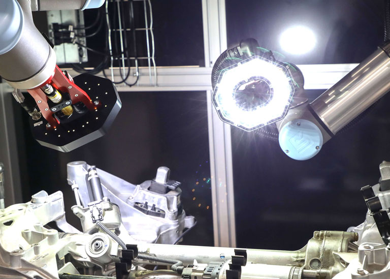
Robots in manufacturing have been used for over sixty years, with the first commercial robots used in mass production in the 1960s – these were leviathans with large, unwieldy pneumatic arms, but they paved the way for what was to come in the 1970s. At this time, it was estimated that the USA had 200 such robots [1] used in manufacturing; by 1980, this was 4,000 – and now there are estimated to be more than 3 million robots in operation [2]. During this time the machine vision industry has grown to provide the “eyes” for the robot. Machine vision uses camera sensor technology to capture images from the environment for analysis to confirm either location (when it comes to robot feedback), quality assessment (from presence verification through to gauging checks) or simply for photo capture for warranty protection.

The automotive industry is a large user of mass-production robots and vision systems. This is primarily due to the overall size of the end unit (i.e. a built car), along with vision systems for confirmation of quality due to the acceptable parts per million failure rate (which is extremely low!). Robots allow repetitive and precise assembly tasks to be completed accurately every time, reducing the need for manual labour and providing a faster speed for manufacturing.

Automating with industrial robots is one of the most effective ways to reduce automotive manufacturing expenses. Factory robots help reduce labour, material, and utility expenses. Robotic automation reduces human involvement in manufacturing, lowering wages, benefits, and worker injury claims.

AI Machine Vision Systems
Deep learning in the context of industrial machine vision teaches robots and machines to do what comes naturally to humans, i.e. to learn by example. New multi-layered “bio-inspired” deep neural networks allow the latest machine vision solutions to mimic the human brain activity in learning a task, thus allowing vision systems to recognise images, perceive trends and understand subtle changes in images that represent defects. [3]

Machine vision performs well at quantitatively measuring a highly structured scene with a consistent camera resolution, optics and lighting. Deep learning can handle defect variations that require an understanding of the tolerable deviations from the control medium, for example, where there are changes in texture, lighting, shading or distortion in the image. Deep-learning vision systems can be used in surface inspection, object recognition, component detection and part identification. AI deep learning helps in situations where traditional machine vision may struggle, such as parts with varying size, shape, contrast and brightness due to production and process constraints.

Augmented Reality in Production Environments
In industrial manufacturing, machine vision is primarily concerned with quality control, which is the automatic visual identification of a component, product, or subassembly to ensure that it is proper. This can refer to measurement, the presence of an object, reading a code, or verifying a print. Combining augmented, mixed reality with automated machine vision operations creates a platform for increased efficiency. There is a shift towards utilising AI machine vision systems (where applicable!) to improve the reliability of some quality control checks in vision systems. Then, combine that assessment with the operator.

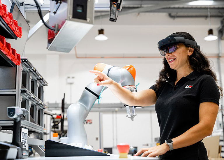
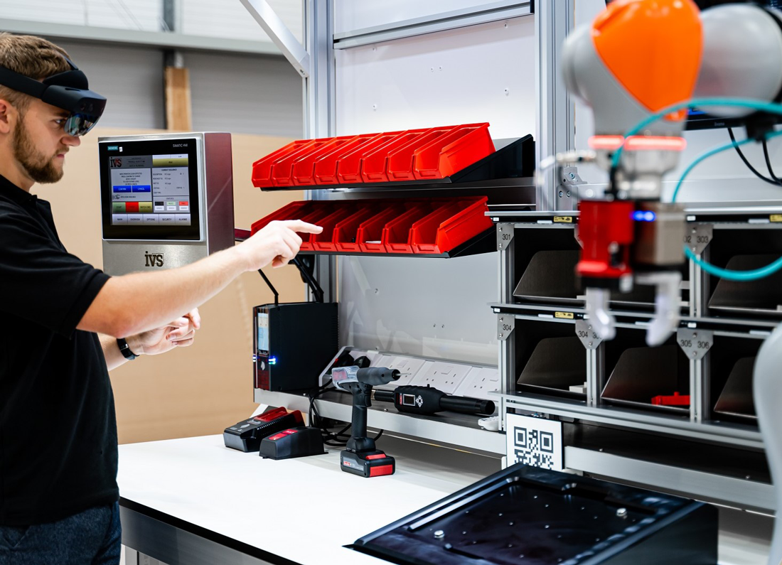
Consider an operator or assembly worker sitting in front of a workstation wearing wearable technology like the HoloLens or Apple Vision Pro (an augmented reality headset). An operator could be putting together a sophisticated unit with several pieces. They can see the tangible objects around them, including components and assemblies. They can still interact with digital content, such as a shared document that updates in real time to the cloud or assembly instructions. That is essentially the promise of mixed reality.

The mixed-reality device uses animated prompts, 3D projections, and instructions to guide the operator through the process. A machine vision camera is situated above the operator, providing a view of the scene below. As each step is completed and a part is assembled, the vision system automatically inspects the product. Pass and fail criteria can be automatically projected into the operator’s field of sight in the mixed reality environment, allowing them to continue building while knowing the part has been inspected. In the event of a rejected part, the operator receives a new sequence “beamed” into their projection, containing instructions on how to proceed with the failed assembly and where to place it. When integrated with machine vision inspection, mixed reality has become a standard aspect of the production process. Data, statistics, and important quality information from the machine vision system are shown in real time in the operator’s field of view.

Robots, AI Vision Systems and Augmented Reality
Let’s fast forward a few years and see what the future looks like. Well, it’s a combination of all these technologies as they continue to develop and mature. So AI vision systems mounted on cobots help with the manual assembly, while the operator wears an augmented reality headset to direct and guide the process for an unskilled worker. Workers are tracked while all tasks are being quality assessed and confirmed, while data is stored for traceability and warranty protection.

In direct automotive manufacturing, vision systems will become easier to use as large AI deep-learning datasets become more available for specific quality control tasks. These datasets will continue to evolve as more automotive and tier one and two suppliers use AI vision to monitor their production, allowing quicker deployment and high-accuracy quality control assessment across the factory floor.


References

Why you should transition your quality inspection from shadowgraphs to automated vision inspection

The shadowgraph used to be the preferred method, or perhaps the only method for the quality control department to check the adherence to measurement data. These typically vertical projectors have a plate bed, with parts laid on it, and the light path is vertical. This allows a silhouette and profile of the part to be shown to the operators as an exact representation of the part in black, but projected at a much higher magnification. These projectors are best for flat, flexible parts, washers, O rings, gaskets and parts that are too small to hold, such as very small shafts, screws etc. They are also used in orthopedic manufacturing to view profiles and edges of joint parts.

So, this old-fashioned method involves projecting a silhouette of the edge of the product or component. This projection is then overlaid with a clear (black-lined) drawing of the product showing some additional areas where the component shouldn’t stray into. The operator chooses the overlay from a bunch available, based on the part number of the part. This is laid over the projection and manually lined up with the tolerances shown as a thick band in key areas for quality checking. For example, if you’re an orthopedic joint manufacturer and are coating your product with an additive material, you might use a shadowgraph to check the edges of the new layer. The shadowgraph will project a magnified representation of the component to compare against.

Some optical comparators and shadowgraphs have developed to a level where they are combined with a more modern graphical user interface (GUI) and are digital to make overlays easier to check, coupled with the ability to take manual measurements.

Ultimately though, all these types of manual shadowgraphs take time to use, are manually intensive and are totally reliant on an operator to make the ultimate decision on what is a pass and a fail. You also have no record of what the projection looked like and the whole process takes time. This all leads to a loss of productivity and makes your Six Sigma quality levels dependent on an operator’s quality check, and as we all know, manual inspection (even 200% manual inspection) is not a reliable method for manufacturers to keep their quality levels in check. Operators get tired and there is a lack of consistency between different people in the quality assessment team.

But for those products with critical-to-quality measurements, the old shadowgraph methodology can now be replaced with a fully automated metrology vision system to reduce the reliance on the operator in making decisions, coupled with the ability to save SPC data and information.

In this case, the integration of ultra-high-resolution vision systems, in tandem with cutting-edge optics and collimated lighting, presents a formidable alternative to manual shadowgraphs, ushering in an era of automation. With this advancement, operators can load the product, press a button, and swiftly obtain automatic results confirming adherence to specified tolerances. Furthermore, all pertinent data can be meticulously recorded, with the option to enable serial number tracking, ensuring the preservation of individual product photos for future warranty claims. This transition not only illuminates manufacturing processes but elevates them to a brighter, six-sigma enhanced quality realm. Moreover, these systems can be rigorously validated to GAMP/ISPE standards, furnishing customers with an unwavering assurance of consistently superior quality outcomes.

For your upcoming quality initiatives or product launches, consider pivoting towards automated vision system machines, transcending the limitations of antiquated shadowgraph technology and operator-dependent assessments. Embrace the superior approach that is now within reach, and steer your manufacturing quality towards a future defined by precision, efficiency, and reliability.

By embracing automated vision systems, manufacturers streamline processes and ensure unparalleled precision and consistency in product quality. This shift represents a pivotal leap forward in manufacturing excellence, empowering businesses to meet and exceed customer quality expectations while navigating the ever-evolving landscape of modern production.

The ultimate guide to Unique Device Identification (UDI) directives for medical devices (and how to comply!)

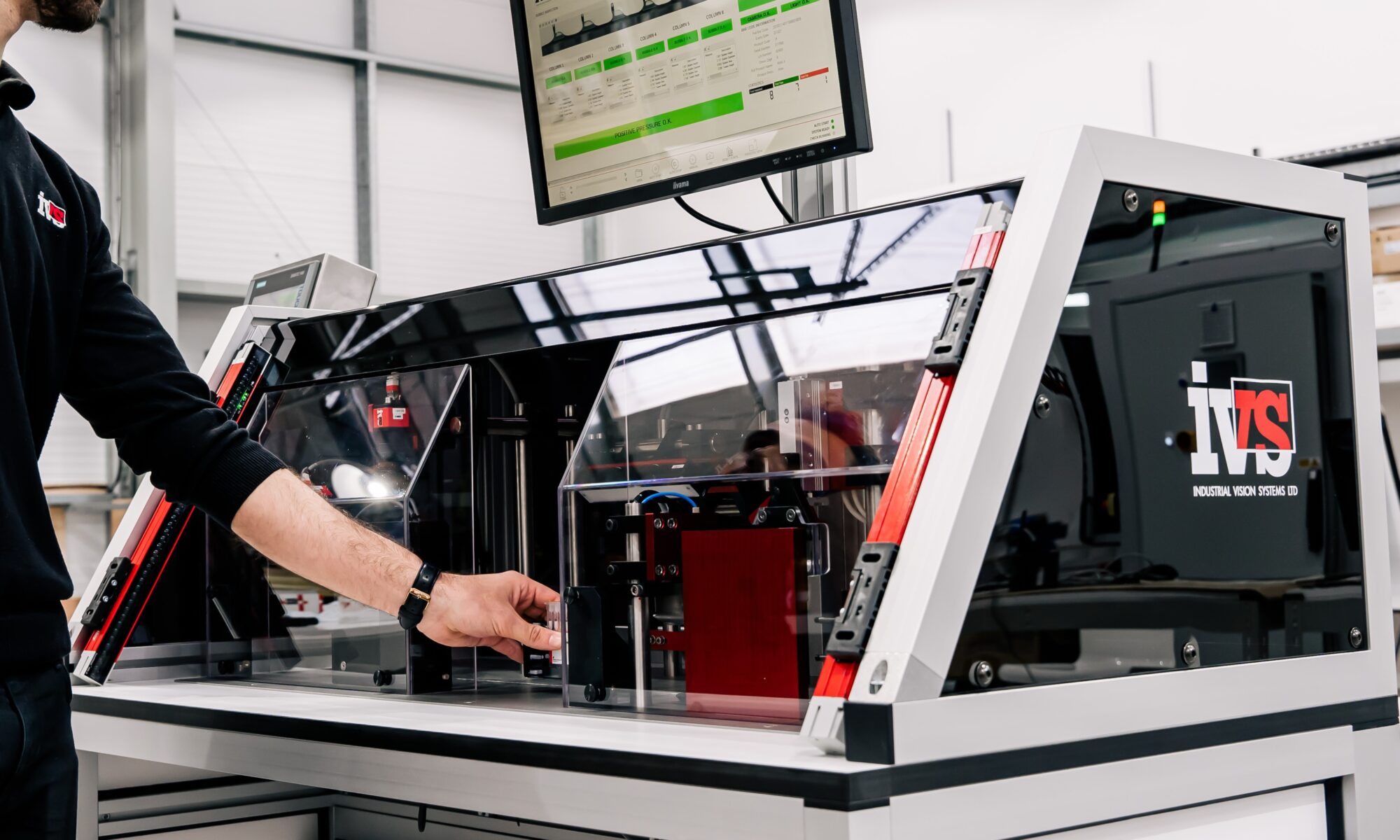
This month, we’re talking about the print you see on medical devices and in-vitro products used for the traceability and serialisation of the product – called the UDI or Unique Device Identification mark. In the ever-evolving world of healthcare, new niche manufacturers and big medical device industrial corporations find themselves at a crossroads. Change has arrived within the Medical Device Regulation, and many large and small companies have yet to strike the right chord, grappling with the choices and steps essential to orchestrate compliance to the latest specifications. Automated vision systems are required at every stage of the production and packaging stages to confirm compliance and adherence to the standards for UDI. Vision systems ensure quality and tracking and provide a visible record (through photo save) of every product stage during production, safeguarding medical devices, orthopaedic and in-vitro product producers.

UDI

What is UDI?

The UDI system identifies medical devices uniformly and consistently throughout their distribution and use by healthcare providers and consumers. Most medical devices are required to have a UDI on their label and packaging, as well as on the product itself for select devices.

Each medical device must have an identification code: the UDI is a one-of-a-kind code that serves as the “access key” to the product information stored on EUDAMED. The UDI code can be numeric or alphanumeric and is divided into two parts:

DI (Device Identifier): A unique, fixed code (maximum of 25 digits) that identifies a device’s version or model and its maker.

Production Identifier (PI): It is a variable code associated with the device’s production data, such as batch number, expiry date, manufacturing date, etc. UDI-DI codes are supplied by authorised agencies such as GS1, HIBCC, ICCBBA, or IFA and can be freely selected by the MD maker.

UDI

UDIs have been phased in over time, beginning with the most dangerous equipment, such as heart valves and pacemakers. So, what’s the latest directive on this?

Navigating the Terrain of MDR and IVDR: Anticipating Challenges

The significant challenges presented by the European Medical Devices Regulation (MDR) 2017/745 have come to the fore since its enactment on May 26th, 2021. This regulatory overhaul supersedes the older EU directives, namely MDD and AIMDD. A pivotal aspect of the MDR is its stringent oversight of medical device manufacturing, compelling the display of a unique code for traceability throughout the supply chain – this allows full traceability through the process from the manufacture of the medical device to the final consumer use.

Adding to the regulatory landscape, the In-Vitro Diagnostic Regulation (IVDR) 2017/746 debuted on May 26th, 2022. This regulation seamlessly replaced the previous In-Vitro Diagnostic Medical Devices (IVDMD) regulation, further shaping the intricate framework governing in-vitro diagnostics. The concurrent implementation of MDR and IVDR ushers in a new era of compliance and adaptability for medical devices and diagnostics stakeholders.

What are the different classes of UDI?

Risk Profile Notify or Self-Assessment Medical Devices In-Vitro Diagnostic Medical Devices
High Risk to Low Risk Notified Body Approval Required Pacemakers, Heart Valves, Implanted cerebral simulators Class III Class D Hepatitis B blood-donor screening, ABO blood grouping
Condoms, Lung ventilators, Bone fixation plate Class IIb Class C Blood glucose self-testing, PSA screening, HLA typing
Dental fillings, Surgical clamps, Tracheomotoy Tubes Class IIa Class B Pregnancy self-testing, urine test strips, cholesterol self-testing
Self-Assessment Wheelchairs, spectacles, stethoscopes Class I Class A Clinical chemical analysers, specimen receptacles, prepared selective culture media

Deadlines for the classification to come into force

Implementing the new laws substantially influences many medical devices and in-vitro device companies, which is why the specified compliance dates have been prioritised based on the risk class to which the devices belong. Medical device manufacturers must adopt automated inspection into their processes to track and confirm that the codes are on their products in time for the impending deadlines.

The Act recognises four types of medical devices and four categories of in-vitro devices, which are classified in ascending order based on the degree of risk they provide to public health or the patient.

2023 2025 2027
UDI marking on DM Class III Class I
Direct UDI marking on reusable DM Class III Class II Class I
UDI marking on in-vitro devices (IVD) Class D Class C & B Class A

The term “unique” does not imply that each medical device must be serialised individually but must display a reference to the product placed on the market. In fact, unlike in the pharmaceutical industry, serialisation of devices in the EU is only required for active implantable devices such as pacemakers and defibrillators.

EUDAMED is the European Commission’s IT system for implementing Regulation (EU) 2017/745 on medical devices (MDR) and Regulation (EU) 2017/746 on in-vitro diagnostic medical devices (IVDR). The EUDAMED system contains a central database for medical and in-vitro devices, which is made up of six modules.

EUDAMED is currently used on a voluntary basis for modules that have been made available. The connection to EUDAMED must take place within six months of the release of all platform modules that are fully functioning.

Data can be exchanged with EUDAMED in three methods, depending on the amount of data to be loaded and the required level of automation.

The “visible” format of the UDI is the UDI Carrier, which must contain legible characters in both HRI and AIDC formats. The UDI must be displayed on the device’s label, primary packaging, and all upper packaging layers representing a sealable unit.

These rules mean medical device manufacturers need reliable, traceable automated vision inspection to provide the track and trace capability for automatic aggregation and confirmation of the UDI process.

The UDI is a critical element of the medical device manufacturing process, and therefore, applying vision systems with automated Optical Character Recognition (OCR) and Optical Character Verification (OCV) in conjunction with Print Quality Inspection (PQI) is required for manufacturers to guarantee that they comply with the legislation.

But what are the differences between Optical Character Recognition (OCR) vs Optical Character Verification (OCV) vs Print Quality Inspection (PQI)?
We get asked this often, and how you apply the vision system technology is critical for traceability. To comply with UDI legislation, medical device manufacturers must check that their products comply with the requirements and track them through the production process. Whether you use OCR, OCV, or PQI depends on the manufacturer stage and where you are in the manufacturing process.

UDI

Optical Character Recognition (OCR)

Optical character recognition is based on the need to identify a character from the image presented, effectively recognise the character, and output a string based on the characters “read”. The vision system has no prior knowledge of the string. It therefore mimics the human behaviour of reading from left to right (or any other orientation) the sequence it sees.
You can find more information on OCR here.

Optical Character Verification (OCV)
Optical character verification differs from recognition as the vision system has been told in advance what string it should expect to “read”, and usually, with a class of characters it should expect in a given location. Most UDI vision systems will utilise OCV, as opposed to OCR, as the master database, line PLC (Programmable Logic Controller), cell PLC and laser/label printer should all know what will be marked. Therefore, the UDI vision system checks that the characters marked are verified and readable in that correct location (and have been marked). This then allows for the traceability through the process through nodes of OCV systems throughout the production line.
You can find more information on OCV here.

Print Quality Inspection (PQI)

Print quality inspection methods differ considerably from the identification methods discussed so far. The idea is straightforward: an ideal template of the print to be verified is stored; this template does not necessarily have to be taken from a physically existing ‘‘masterpiece’’, it could also be computer-generated. Next, an image containing all the differences between the ideal template and the current test piece is created. Simply, this can be done by subtracting the reference image from the current image. But applying this method directly in a real-world context will show very quickly that it will always detect considerable deviations between the reference template and test piece, regardless of the actual print quality. This is a consequence of inevitable position variations and image capture and transfer inaccuracies. A change in position by a single pixel will result in conspicuous print defects along every edge of the image. So, print quality inspection is looking for the difference between the print trained and the print found. Therefore, PQI will pick up missing parts of characters, breaks in characters, streaks, lines across the pack and general gross defects of the print.

You can find more information on PQI here.

UDI
UDI

What about Artificial Intelligence (AI) with OCR/OCV for UDI?

Where we’ve been discussing OCR and OCV, we’ve assumed that the training class is based either on a standard OCR font (a unique sans-serif font created in the early days of vision inspection to provide a consistent font, recognisable by humans and vision systems), or a trainable, repeatable fixed font. OCR with AI is a comprehensive deep-learning-based OCR (or OCV) method. This innovative technology advances machine vision towards human reading. AI OCR can localise characters far more robustly than conventional algorithms, regardless of orientation, font type, or polarity. The capacity to automatically arrange characters enables the recognition of entire words. This significantly improves recognition performance because misinterpreting characters with similar appearances is avoided. Large images can be handled more robustly with this technique, and the AI OCR result offers a list of character candidates with matching confidence ratings, which can be utilised to improve the recognition results further. Users benefit from enhanced overall stability and the opportunity to address a broader range of potential applications due to expanded character support. Sometimes, this approach can be used. However, it should be noted that it can make validation difficult due to the need for a data set prior to learning, compared to a traditional setup.

Do all my UDI vision inspection systems require validation?

Yes, all the vision systems for UDI inspection must be validated to GAMP/ISPE levels. Having the systems in place is one thing, but the formal testing and validation paperwork is needed to comply fully with the legislation. You can find more information on validation in one of our blog articles here.

UDI
UDI

Industrial vision systems allow for the 100% inspection of medical devices at high production speeds, providing a final gatekeeper to prevent any rogue product from exiting the factory gates. These systems, in combination with factory information communication and track & trace capability, allow the complete tracking of products to UDI standards through the factory process.

Machine vision vs computer vision vs image processing

We’re often asked – what’s the difference between machine vision and computer vision, and how do they both compare with image processing? It’s a valid question as the two seemingly similar fields of machine vision and computer vision both relate to the interpretation of digital images to produce a result from the image processing of photos or images.

What is machine vision?
Machine vision has become a key technology in the area of quality control and inspection in manufacturing. This is due to increasing quality demands and the improvements it offers over and above human vision and manual operation.

Definition
It is the ability of a machine to consequentially sense an object, capture an image of that object, and then process and analyse the information for decision-making.

In essence, machine vision enables manufacturing equipment to ‘see’ and ‘think’. It is an exciting field that combines technologies and processes to automate complex or mundane visual inspection tasks and precisely guide manufacturing activity. In an industrial context, it is often referred to as ‘Industrial Vision’ or ‘Vision Systems’. As the raw image in machine vision are generally captured by a camera connected to the system in “real-time” (compared to computer vision), the disciplines of physics relating to optical technology, lighting and filtering are also part of the understanding in the machine vision world.

So, how does this compare to computer vision and image processing?
There is a great deal of overlap between the various disciplines, but there are clear distinctions between the groups.

Input Output
Image processing Image is processed using algorithms to correct, edit or process an image to create a new better image. Enhanced image is returned.
Computer vision Image/video is analysed using algorithms in often uncontrollable/unpredictable circumstances. Image understanding, prediction & learning to inform actions such as segmentation, recognition & reconstruction.
Machine vision Use of camera/video to analyse images in industrial settings under more predictable circumstances. Image understanding & learning to inform manufacturing processes.

Image processing has its roots in neurobiology and scientific analysis. This was primarily down to the limitations of processor speeds when image processing came into the fore in the 1970’s and 1980’s—for example, processing single images following the capture from a microscope-mounted camera.

When processors became quicker and algorithms for image processing became more adept at high throughput analysis, image processing moved into the industrial environment, and industrial line control was added to the mix. For the first time, this allowed an analysis of components, parts and assemblies as part of an automated assembly line to be quantified, checked and routed dependent on the quality assessment, so machine vision (the “eyes of the production line”) was born. Unsurprisingly, the first industry to adopt this technology en mass was the PCB and semiconductor manufacturers, as the enormous boom in electronics took place during the 1980s.

Computer vision crosses the two disciplines, creating a Venn diagram of overlap between the three areas, as shown below.

Machine vision vs computer vision vs image processing

As you can see, the work on artificial intelligence relating to deep learning has its roots in computer vision. Still, over the last few years, this has moved over into machine vision, as the image processing learnt from biological vision, coupled with cognitive vision moves slowly into the area of general purpose machine vision & vision systems. It’s rarely a two-way street, but some machine vision research moves back into computer vision and general image processing worlds. Given the more extensive reach of the computer vision industry, compared to the more niche machine vision industry, new algorithms and developments are driven by the broader computer vision industry.

Machine vision, computer vision and image processing are now broadly intertwined, and the developments across each sector have a knock-on effect on the growth of new algorithms in each discipline.

IVS helps global contact lens manufacturers achieve error-free lenses (at speed!)

This month, we are talking about automated visual inspection of cosmetic defects in contact lens inspection, a major area of expertise in the IVS portfolio. Contact lens production falls between medical device manufacturing and pharmaceuticals manufacturing, but it does mean that it falls within the GAMP/ISPE/FDA validation requirements when it comes to manufacturing quality and line validation.

The use of vision technology for the inspection of contact lenses is intricate. Due to the wide variety of lens profiles, powers, and types (such as spherical, toric, aspherical etc.), manufacturers historically relied on human operators to visually verify each lens before it was shipped to a customer. Cosmetic defects in lenses range from scratches and inclusions, through to edge defects, mould polymerisation problems and overall deformity in the contact lens.

The Challenge: Manual Checks are Prone to Human-Error and are Slow!

The global contact lens industry must maintain the highest standards of quality due to the specialist nature of its products. Errors or faults in contact lenses can lead to negative recalls, financial losses, or a drop in brand loyalty and integrity – all issues that could otherwise be very difficult to rectify. However, manually checking lenses has become extremely time-consuming, inefficient, and error-prone. Due to the brain’s tendency to rectify errors naturally, human error is a common cause of oversights. This makes it next to impossible to spot faults by hand, therefore many errors are missed, and contact lens defects can be passed to the consumer.

Coupled with this, many global contact lens manufacturing brands run their production at high speed, which means using human inspectors simply becomes untenable based on the volume and speed of production; so in the last twenty-five years, contact lens manufacturers have moved to high-speed, high-accuracy automated visual inspection, negating the need for manual checks.

To ensure their products’ quality, accuracy, and consistency, many of the world’s top contact lens manufacturing brands have turned to IVS to solve their automated inspection and verification problems. This can be either wet or dry contact lens inspection, depending on the specific nature of the production process.

The Solution: Minimize Errors and Ensure Quality Through IVS Automated Visual Inspection

IVS contact lens inspection solutions have been developed over many years based on a deep and long heritage in contact lens inspection and the required FDA/GAMP validation. The vision system drills down on the specific contact lens defects, allowing finite, highly accurate quality checks and inspection coupled with the latest generation AI vision inspection techniques. This allows the maximum yield achievable, coupled with full reporting and statistical analysis, to give the data feedback to the factory information system, providing real-time, reliable information to the contact lens manufacturer. Failed lenses are rejected, allowing 100% quality inspected contact lenses to be packed and shipped.

IVS have inspection systems for manual load, automated and high-speed contact lens inspection, allowing our solutions to cover the full range of contact lens manufacturers – from small start-ups to the major high-level production volume producers. Whatever the size of your contact lens production, we have validated solutions to FDA/ISPE/GAMP for automated contact lens inspection.

Contact lens manufacturers now have no requirement for manual visual inspection by operators; this can all be achieved through validated automated visual inspection of cosmetic defects, providing high-yield, high-throughput quality inspection results.

More details: https://www.industrialvision.co.uk/wp-content/uploads/2023/05/IVS-Lens-Inspection-Solutions.pdf

How vision systems are deployed for 100% cosmetic defect detection (with examples)

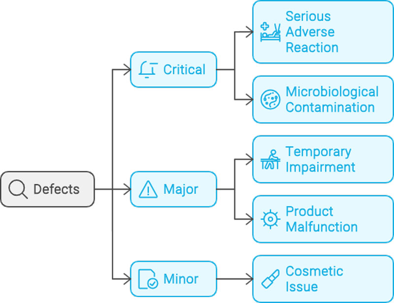
Cosmetic defects are the bane of manufacturers across all industries. Producing a product with the correct quality in terms of measurement, assembly, form, fit, and function is one thing – but cosmetic defects are more easily noticed and flagged by the customer and end-user of the product. Most of the time, they have no detrimental effect on the use or function of the product, component or sub-assembly, they just don’t look good! They are notoriously difficult for an inspection operator to spot and are therefore harder to check using traditional quality control methods. The parts can be checked on a batch or 100% basis for measurement and metrology checks, but you can’t batch-check for a single cosmetic defect in a high-speed production process. So for mass production medical device manufacturing at 300-500 parts per minute, using vision systems for automated cosmetic defect inspection is the only approach.

From medical device manufacturers, cosmetic defects might manifest themselves as inclusions, black spots, scratches, marks, chips, dents or a foreign body on the part. For automotive manufacturers, it could be the wrong position of a stitch on a seat body, defects on a component, a mark on a sub-assembly, or the gap and flush of the panels on a vehicle.

Using vision systems for automated cosmetic inspection is especially important for products going to the Japanese and the Asian markets. These markets are particularly sensitive to cosmetic issues on products, and medical device manufacturers need to use vision systems to 100% inspect every product produced to confirm that no cosmetic defects are present on their products. This could be syringe bodies, vials, needle tips, ampules, injector pen parts, contact lenses, medical components and wound care products. All need checking at speed during the manufacturing and high-speed assembly processes.

How are vision systems applied for automated cosmetic checks?

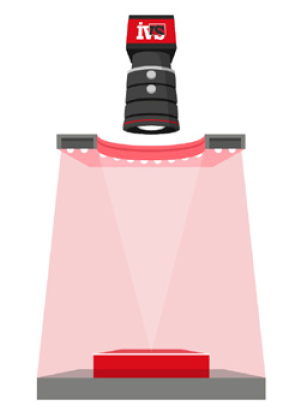
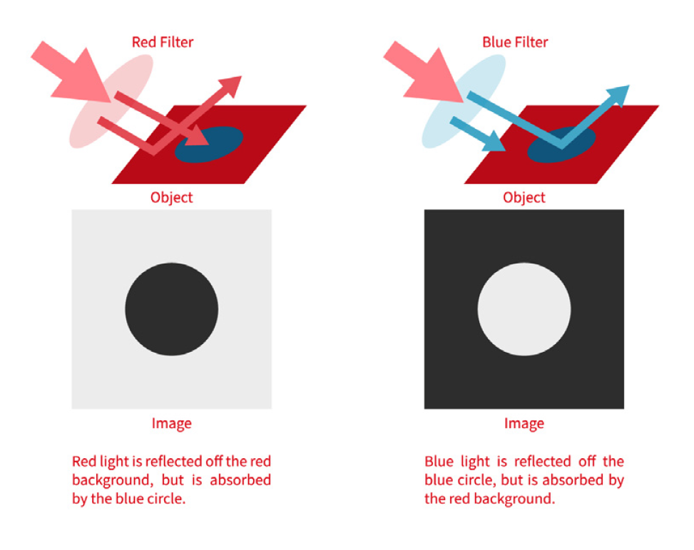
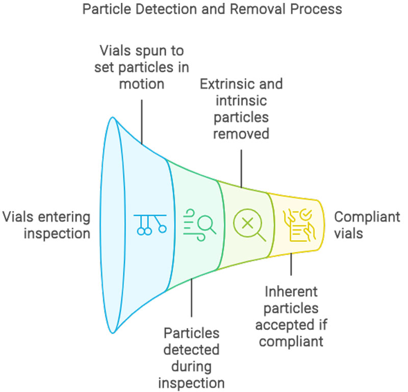
The key to applying vision systems for cosmetic visual inspection is the combination of camera resolutions, optics (normally telecentric in nature) and filters to bring out the specific defect to provide the ability to segment it from the natural variation and background of the product. Depending on the type of cosmetic defect that is being checked, it may also require a combination of either linescan, areascan or 3D camera acquisition. For example, syringe bodies or vials can be spun in front of a linescan camera to provide an “unrolled” view of the entire surface of the product.

Let’s drill down on some of the specific elements which are used, using the syringe body as a reference (though these methods can be applied to other product groups):

Absorbing defects

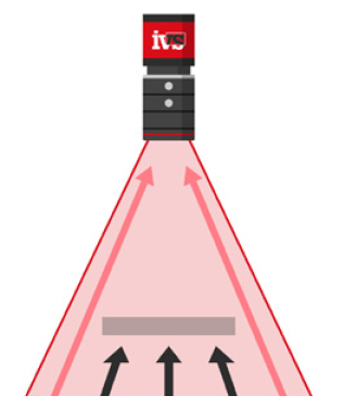
These defects are typically impurities, particulates, fibers and bubble. This needs a lighting technique with linescan to provide a contrasting element for these defects:

Hidden defects

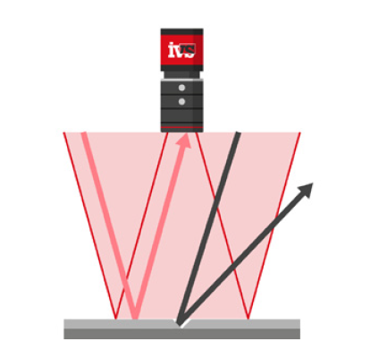
These defects are typically “hidden” from view via the linescan method and so using a direct on-axis approach with multiple captures from an areascan sensor will provide the ability to notice surface defects such as white marks (on clear and glass products) and bubbles.

Cracks and scratch defects

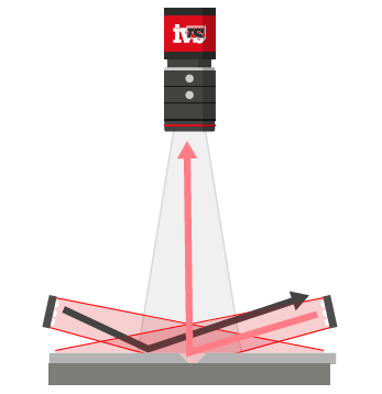
A number of approaches can be taken for this, but typically applying an axial illuminiation with a combination of linescan rotation will provide the ability to identify cracks, scratches and clear fragments.

Why do we use telecentric optics in cosmetic defect detection?

Telecentric lenses are optics that only gather collimated light ray bundles (those that are parallel to the optical axis), hence avoiding perspective distortions. Because only rays parallel to the optical axis are admitted, telecentric lens magnification is independent of object position. Due to this distinguishing property, telecentric lenses are ideal for measuring and cosmetic inspection applications where perspective problems and variations in magnification might result in inconsistent measurements. The front element of a telecentric lens must be at least as large as the intended field of view due to its construction, rendering telecentric lenses insufficient for imaging very large components.

Fixed focal length lenses are entocentric, catching rays that diverge from the optical axis. This allows them to span wide fields of view, but because magnification varies with working distance, these lenses are not suitable for determining the real size of an item. Therefore, telecentric optics are well suited for cosmetic and surface defect detection, often combined with collimated lighting to provide the perfect silhouette of a product.

In conclusion, machine vision systems can be deployed effectively for 100% automated cosmetic defect detection. By combining the correct optics, lighting, filters and camera technology, manufacturers can use a robust method for 100% automated visual inspection of cosmetic and surface defects.

The complete guide to Artificial Intelligence (AI) and Deep Learning (DL) for machine vision systems.

Where are we at, and what is the future?

We had a break from the blog last month while we worked on this latest piece, as it’s a bit of a beast. This month we discuss artificial intelligence (AI) for machine vision systems. An area with much hype due to the introduction of AI language models such as ChatGPT and AI image models like DALLE. AI is starting to take hold for vision systems, but what’s it all about? And is it viable?

Where are we at?

Let’s start at the beginning. The term “AI” is an addendum for a process that has been around for the last twenty years in machine vision but has only now become more prolific (or should we say, the technology has matured to the point of mass deployment). We provided vision systems in the early 00’s using low-level neural networks for feature differentiation and classification. These were primarily used for simple segmentation and character verification. These networks were basic and had limited capability. Nonetheless, the process we used then to train the network is the same as it is now, but on a much larger scale. Back then, we called it a “neural network”; now it’s termed artificial intelligence.

The term artificial intelligence is coined as the network has some level of “intelligence” to learn by example and expand its knowledge on iterative training levels. The initial research into computer vision AI discovered that human vision has a hierarchical structure on how neurons respond to various stimuli. Simple features, such as edges, are detected by neurons, which then feed into more complex features, such as shapes, which finally feed into more complex visual representations. This builds individual blocks into “images” the brain can perceive. You can think of pixel data in industrial vision systems as the building blocks of synthetic image data. Pixel data is collected on the image sensor and transmitted to the processor as millions of individual pixels of differing greyscale or colour. For example, a line is simply a collection of like-level pixels in a row with edges that transition pixel by pixel in grey level difference to an adjacent location.

Neural networks AI vision attempts to recreate how the human brain learns edges, shapes and structures. Neural networks consist of layers of processing units. The sole function of the first layer is to receive the input signals and transfer them to the next layer and so on. The following layers are called “hidden layers”, because they are not directly visible to the user. These do the actual processing of the signals. The final layer translates the internal representation of the pattern created by this processing into an output signal, directly encoding the class membership of the input pattern. Neural networks of this type can realise arbitrarily complex relationships between feature values and class designations. The relationship incorporated in the network depends on the weights of the connections between the layers and the number of layers – and can be derived by special training algorithms from a set of training patterns. The end result is a “web” of connections between the networks in a non-linear fashion. All of this is to try and mimic how the brain operates in learning.

With this information in hand, vision engineering developers have been concentrating their efforts on digitally reproducing human neural architecture, which is how the development of AI came into being. When it comes to perceiving and analysing visual stimuli, computer vision systems employ a hierarchical approach, just like their biological counterparts do. Traditional machine vision inspection continued in this vein, but AI requires a holistic view of all the data to compare and develop against.

So, the last five years have seen an explosion in the development of artificial intelligence, deep learning vision systems. These systems are based on neural network development in computer vision in tandem with the development of AI in other software engineering fields. All are generally built on an automatic differentiation library to implement neural networks in a simple, easy-to-configure solution. Deep learning AI vision solutions incorporate artificial intelligence-driven defect finding, combined with visual and statistical correlations, to help pinpoint the core cause of a quality control problem.

To keep up with this development, vision systems have evolved into manufacturing AI and data gathering platforms, as the need for vision data for training becomes an essential element for all AI vision systems compared to deploying traditional machine vision algorithms. Traditional vision algorithms still need image data for development, but not to the same extent as needed for deep learning. This means vision platforms have developed to integrate visual and parametric data into a single digital thread from the development stage of the vision project all the way through production quality control deployment on the shop floor.

In tandem with the proliferation of the potential use of AI in vision systems is the explosion in suppliers of data-gathering “AI platforms”. These systems are more of a housekeeping exercise for image gathering, segmentation and human classification before the submission to the neural network, rather than being a quantum leap in image processing or a clear differential compared to traditional machine vision. Note: most of these companies have “AI” in their titles. These platforms allow for clear presentation of the images and the easy submission to the network for computation of the neural algorithm. Still, all are based on the same overall architecture.

The deep learning frameworks – Tensorflow or PyTorch – what are they?

Tensorflow and PyTorch are the two main deep learning frameworks developers of machine vision AI systems use. Each was developed by Google and Facebook, respectively. They are used as a base for developing the AI models at a low level, generally with a graphical user interface (GUI) above it for image sorting.

TensorFlow is a symbolic math toolkit that is best suited for dataflow programming across a variety of workloads. It provides many abstraction levels for modelling and training. It’s a promising and rapidly growing deep learning solution for machine vision developers. It provides a flexible and comprehensive ecosystem of community resources, libraries, and tools for building and deploying machine-learning apps. Recently, Tensorflow has integrated Keras into the framework, a precursor to Tensorflow.

PyTorch is a highly optimised deep learning tensor library built on Python and Torch. Its primary use is for applications that use graphics processing units (GPUs) and central processing units (CPUs). Vision system vendors favour PyTorch over other Deep Learning frameworks such as TensorFlow and Keras because it employs dynamic computation networks and is entirely written in Python. It gives researchers, software engineers, and neural network debuggers the ability to test and run sections of the code in real-time. Because of this, users do not have to wait for the entirety of the code to be developed before determining whether or not a portion of the code works.

Whichever solution is used for deployment, the same pros and cons apply in general to machine vision solutions utilising deep learning.

What are the pros and cons of using artificial intelligence deep learning in machine vision systems?

Well, there are a few key takeaways when considering using artificial intelligence deep learning in vision systems. These offer pros and cons when considering whether AI is the appropriate tool for industrial vision system deployment.

Cons

Industrial machine vision systems must have high yield, so we are talking 100% correct identification of faults, in substitute for accepting some level of false failure rate. There is always a trade-off in this process in setting up vision systems to ensure you err on the side of caution so that real failures are guaranteed to be picked up and automatically rejected by the vision system. But with AI inspection, the yields are far from perfect, primarily because the user has no control of the processing functionality that has made the decision on what is deemed a failure. A result of pass or fail is simply given for the outcome. The neural network having been trained from a vast array of both good and bad failures. This “low” yield (though still above 96%) is absolutely fine for most requirements of deep learning (e.g. e-commerce, language models, general computer vision), but for industrial machine vision, this is not acceptable in most application requirements. This needs to be considered when thinking about deploying deep learning.

It takes a lot of image data. Sometimes thousands, or tens of thousands of training images are required for the AI machine vision system to start the process. This shouldn’t be underestimated. And think about the implications for deployment in a manufacturing facility –you have to install and run the system to gather data before the learning part can begin. With traditional machine vision solutions, this is not the case, development can be completed before deployment, so the time-to-market is quicker.

Most processing is completed on reduced-resolution images. It should be understood that most (if not all) deep learning vision systems will reduce the image size down to a manageable size to process in a timely manner. Therefore, resolution is immediately lost from a mega-pixel resolution image down to a few hundred pixels. Data is compromised and lost.

There are no existing data sets for the specific vision system task. Unlike AI deep learning vision systems used in other industries, such as driverless cars or crowd scene detection, there are usually no pre-defined data sets to work from. In those industries, if you want to detect a “cat”, “dog”, or “human”, there is available data sources for fast-tracking the development of your AI vision system. Invariably in industrial machine vision, we look at a specific widget or part fault with no pre-determined visual data source to refer to. Therefore, the image data has to be collected, sorted and trained.

You need good, bad and test images. You need to be very careful in selecting the images into the correct category for processing. A “bad” image in the “good” pile of 10,000 images is hard to spot and will train the network to recognise bad as good. So, the deep learning system is only as good as the data provided to it for training and how it is categorised. You must also have a set of reference images to test the network with.

You sometimes don’t get definitive data on the reason for failure. You can think of the AI deep learning algorithm as a black box. So, you feed the data in and it will provide a result. Most of the time you won’t know why it passed or failed a part, or for what reason, only that it did. This makes deploying such AI vision systems into validated industries (such as medical devices, life sciences and pharmaceuticals) problematic.

You need a very decent GPU & PC system for training. A standard PC won’t be sufficient for the processing required in training the neural network. While the PC used for the runtime need be nothing special, your developers will need a high graphics memory PC with a top-of-the-range processer. Don’t underestimate this.

Pros

They do make good decisions in challenging circumstances. Imagine your part requiring automated inspection has a supplier constantly supplying a changing surface texture for your widget. This would be a headache for traditional vision systems, which is almost unsolvable. For AI machine vision, this sort of application is naturally suited.

They are great for anomaly detection which is out of the ordinary. One of the main benefits of AI-based vision systems is the ability to spot a defect that has never been seen before and is “left field” from what was expected. With traditional machine vision systems, the algorithm is developed to predict a specific condition, be it the grey scale of a feature, the size in pixels which deems a part to fail, or the colour match to confirm a good part. But if your part in a million that is a failure has a slight flaw that hasn’t been accounted for, the traditional machine vision system might miss it, whereas the AI deep learning machine vision system might well spot it.

They are useful as a secondary inspection tactic. You’ve exhausted all traditional methods of image processing, but you still have a small percentage of faults which are hard to classify against your known classification database. You have the image data, and the part fails when it should, but you want to drill down to complete a final analysis to improve your yield even more. This is the perfect scenario for AI deep learning deployment. You have the data, understand the fault and can train on lower-resolution segments for more precise classification. This is probably where AI deep learning vision adoption growth will increase over the coming years.

They are helpful when traditional algorithms can’t be used. You’ve tried all conventional segmentation methods, pixel measurement, colour matching, character verification, surface inspection or general analysis – nothing works! This is where AI can step in. The probable cause of the traditional algorithms not operating is the consistency in the part itself which is when deep learning should be tried.

Finally, it might just be the case that deep learning AI is not required for the vision system application. Traditional vision system algorithms are still being developed. They are entirely appropriate to use in many applications where deep learning has recently become the first point of call for solving the machine vision requirement. Think of artificial intelligence in vision systems as a great supplement and a potential tool in the armoury, but to be used wisely and appropriately for the correct machine vision application.

Learn more about Artificial Intelligence (AI) Deep Learning here:

View Page

Automated Vision Metrology: The Future of Manufacturing Quality Control

In-line visual quality control is more crucial than ever in today’s competitive medical device production environment. To keep ahead of the competition, manufacturers must ensure that their products fulfil the highest standards. One of the most effective ways to attain this goal is through automated vision metrology using vision technology.

So what do we mean by this? There are several traditional methods that a quality manager uses to keep tabs on the production quality. In the past, this would have been the use of a collection of slow CMM metrology machines to inspection the product one at a time. CMMs measure the coordinates of points on a part using a touch probe. This information can then be used to calculate the dimensions, surface quality and tolerances of the part. So we are not talking about high-speed vision inspection solutions in this context, but the precise, micron level, precision metrology inspection for measurements and surface defects.

The use of computer-controlled vision inspection equipment to measure and examine products is known as automated vision metrology. These vision systems offer several advantages over manual inspection CMM-type probing methods. For starters, automated metrology is faster. This is due to the fact that machines can perform measurements with great precision and repeatability at speed, as there is no need to touch the product, it’s non-contact vision assessment. Second, real-time inspection of parts is possible with automated metrology. This enables firms to detect and rectify flaws early in the manufacturing process, before they become costly issues.

Advantages of Automated Vision Metrology
The use of automated metrology in manufacturing has many intrinsic benefits. These include:

  • Decreased inspection time: Compared to manual inspection procedures, automated vision metrology systems can inspect parts significantly faster. This can save a significant amount of time during the manufacturing process.
  • Specific CTQ: Vision inspection systems can be set to measure specific critical to quality elements with great precision and reproducibility.
  • Non-contact vision inspection: As the vision camera system has no need to touch the product, it has no chance of scratching or adding to the surface quality problems which a touch probe inevitably has. This is especially important in industries such as orthopaedic joint and medical device tooling manufacturing.
  • Enhanced productivity: Automated vision metrology systems can be equipped with autoloaders, allowing for the fast throughput of products without the need for an operator to manually load a product into a costly fixture. Manufacturers can focus on other tasks that demand human judgement and inventiveness by freeing up human workers from manual inspection tasks.

Modern production relies heavily on automated vision metrology. It has several advantages, including enhanced accuracy, less inspection time, improved quality control, increased production, and higher product quality. With automated loading options now readily available, speed of inspection for precision metrology measurements can be completed at real production rates.

Overall, automated vision metrology is a potent tool for improving the quality and efficiency of production processes. It is an excellent addition to any manufacturing organisation wanting to increase quality control at speed, and make inspection more efficient compared to traditional CMM probing methods.

Clinical insight: 3 ways to minimise automated inspection errors in your medical device production line

Your vision system monitoring your production quality is finally validated and running 24/7, with the PQ behind you it’s time to relax. Or so you thought! It’s important that vision systems are not simply consigned to maintenance without an understanding of the potential automated inspection errors and what to look out for once your machine vision system is installed and running. These are three immediate ways to minimise inspection errors in your medical device, pharma or life science vision inspection solution.

1. Vision system light monitor.
As part of the installation of the vision system, most modern machine vision solutions in medical device manufacturing will have light controllers and the ability to compensate for any changes in the light degradation over time. Fading is a slow process but needs to be monitored. LEDs are made up of various materials such as semiconductors, substrates, encapsulants, and connectors. Over time, these materials can degrade, leading to reduced light output and colour shift. It’s important in a validated solution to understand these issues and have either an automated approach to the changing light condition through close loop control of grey level monitoring, or a manual assessment on a regular interval. It’s something to definitely keep an eye on.

2. Calibration pieces.
For a vision machines preforming automated metrology inspection the calibration is an important aspect. The calibration process will have been defined as part of the validation and production plan. Typically the calibration of a vision system will normally in the form of a calibrated slide with graticules, a datum sphere or a machined piece with traceability certification. Following from this would have been the MSA Type 1 Gauge Studies, this the starting point prior to a G R&R to determine the difference between an average set of measurements and a reference value (bias) of the vision system. Finally the system would be validated with the a Gauge R&R, which is an industry-standard methodology used to investigate the repeatability and reproducibility of the measurement system. So following this the calibration piece will be a critical part of the automated inspection calibration process. It’s important to store the calibration piece carefully, use it as determined from the validation process and keep it clean and free from debris. Make sure your calibration pieces are protected.

3. Preventative maintenance.
Vision system preventative maintenance is essential in the manufacturing of medical devices because it helps to ensure that the vision systems performs effectively over the intended lifespan. Medical devices are used to diagnose, treat, and monitor patients, and they play an important part in the delivery of healthcare. If these devices fail, malfunction, or are not properly calibrated, substantial consequences can occur, including patient damage, higher healthcare costs, and legal culpability for the manufacturer. Therefore, any automated machine vision system which is making a call on the quality of the product (at speed), must be maintained and checked regularly. Preventative maintenance of the vision systems involves inspecting, testing, cleaning, and calibrating the system on a regular basis, as well as replacing old or damaged parts.

Medical device makers benefit from implementing a preventative maintenance for the vision system in the following ways –
Continued reliability: Regular maintenance of the machine vision system can help identify and address potential issues before they become serious problems, reducing the risk of device failure and increasing device reliability.
Extend operational lifespan: Regular maintenance can help extend the lifespan of the vision system, reducing the need for costly repairs and replacements.
Ensure regulatory compliance: Medical device manufacturers are required to comply with strict regulatory standards (FDS, GAMP, ISPE) and regular maintenance is an important part of meeting these standards.

These three steps will ultimately help to lessen the exposure of the manufacture to production faults, and stop errors being introduced into the medical devices vision system production process. By reducing errors in the machine vision system the manufacturer can keep production running smoothly, increase yield and reduce downtime.