For manufacturers of medical devices, quality control is no longer a matter of simple spot checks — it’s a regulatory requirement that demands precision, consistency, and traceability. One global manufacturer recently sought to address longstanding issues on its packaging line: errors in labelling, carton completeness, and aggregation processes that could not be reliably caught by human inspectors. Industrial Vision Systems (IVS) was called upon to implement a comprehensive, non-contact machine vision inspection system. The result was a tightly integrated, multi-point solution that brought automated quality control to every stage of the packaging process — from individual labels through to final case loading.
The Challenge: Visual Inspection Across the Packaging Line
Operating under strict international regulations such as ISO13485 and the European MDR, the customer required a robust, end-to-end vision inspection system to:
• Verify correct label placement and content
• Ensure completeness and conformity of each carton
• Inspect aggregated cases to confirm correct load patterns and packaging integrity
• Log inspection data to support full traceability and audit readiness
• Manual checks had proven insufficient — missing occasional errors and adding operational overhead.
IVS’s Integrated Vision Inspection Strategy
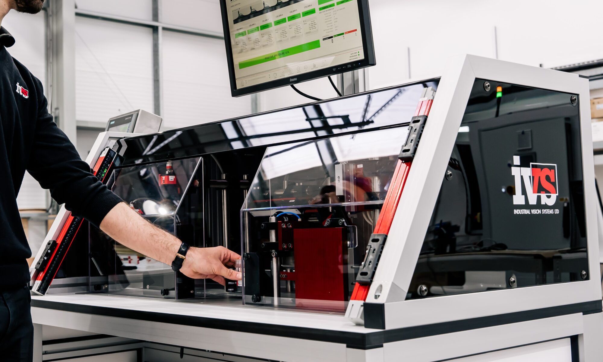
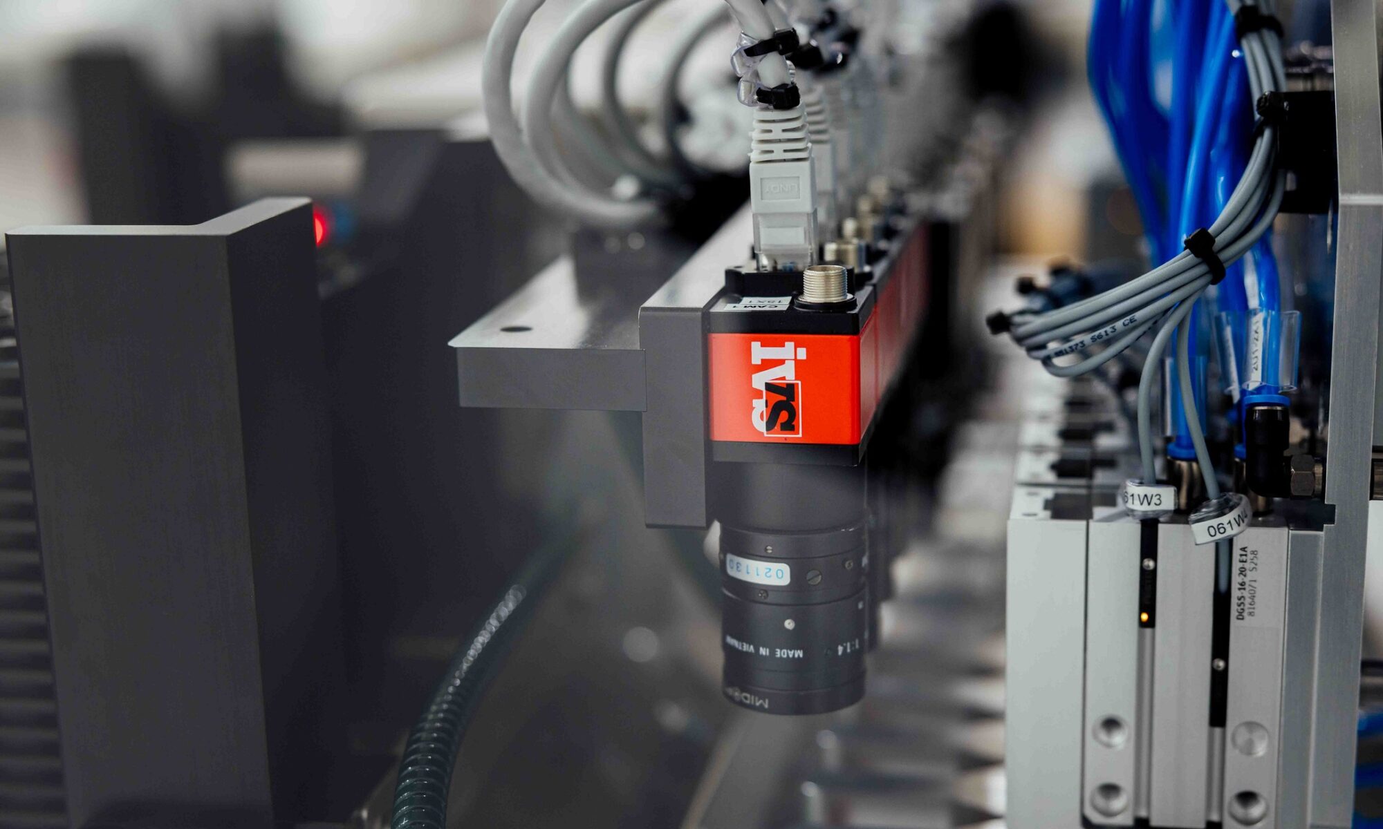
IVS designed and delivered a modular vision inspection system across the client’s primary packaging stages, using high-speed cameras and intelligent image processing software to capture, inspect and validate every product and pack as it moved through the line.
1. Label Inspection Station
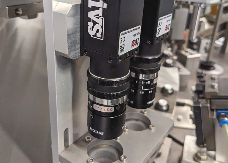
IVS high-resolution cameras were mounted on the labelling unit to verify label presence, alignment, and content legibility on every bottle or vial. Labels with damage, misplacement, or illegible text were identified in real time. Any faulty product was automatically rejected before downstream processing.
2. Carton Inspection Unit
After products were inserted into cartons along with patient information leaflets, a dedicated vision inspection station confirmed that:
• Cartons were present and correctly formed
• Required contents (e.g. device, cap, leaflet) were in place
• Carton flaps were properly closed and sealed
• External carton markings (e.g. pharmacode, branding) were undamaged and correctly oriented
This step removed the risk of incomplete or malformed units reaching customers.
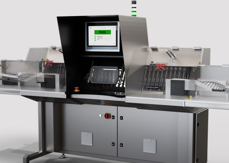
3. Case Aggregation and Final Visual Checks
At the final stage of packaging, as individual cartons were loaded into larger shipping cases, a vision system checked that:
• The correct number and orientation of cartons were present
• Cartons were properly aligned and free from damage
• Outer case seals were intact and packaging was undisturbed
• These checks ensured that every unit shipped was complete, compliant, and visually verified.
Data Logging and Traceability
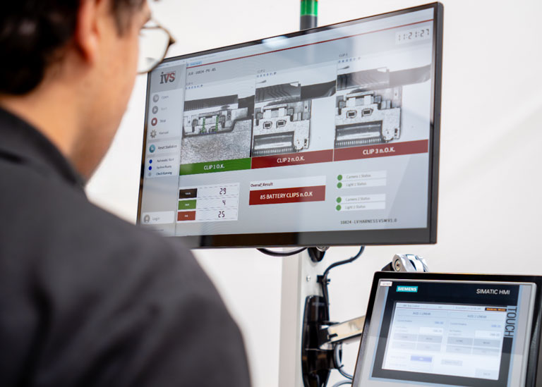
All inspection results — including pass/fail status, timestamp, station location, and stored image snapshots — were automatically logged in a secure database. This created a complete digital audit trail, essential for both internal QA and regulatory inspections.
Operators and QA managers could view this information in real time via IVS’s user interface, or export batch-level data for documentation and trend analysis.
Results Achieved: Quality, Efficiency and Compliance
Following deployment, the manufacturer reported:
• Significant reduction in packaging errors, especially related to missing or incorrectly applied labels and misassembled cartons
• Complete removal of manual visual inspection, freeing up skilled labour for higher-value tasks
• Zero impact on throughput, with inspections running at full line speed
• Stronger audit readiness, with automated records available for every unit produced
Most importantly, the system provided confidence that no incomplete, damaged, or non-compliant product would leave the facility undetected.
Why Machine Vision Is Essential in Medical Device Packaging
Automated machine vision systems are now vital for modern medical packaging operations, offering:
• Contact-free inspection for sterile environments
• Consistent, objective pass/fail decisions
• Detection of visual defects too subtle for human eyes
• Scalable inspection across multiple packaging formats
• Real-time correction via integrated reject systems
For medical device manufacturers under regulatory pressure, this represents a vital tool in reducing risk while improving operational efficiency.
Key Capabilities of the IVS System
The IVS-installed system includes:
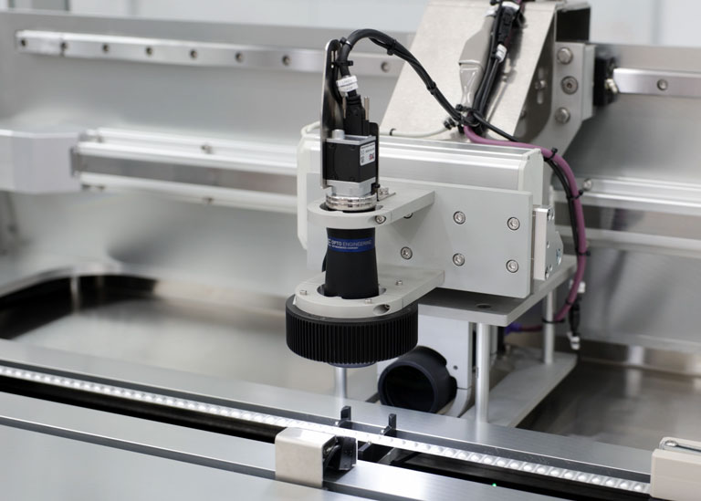
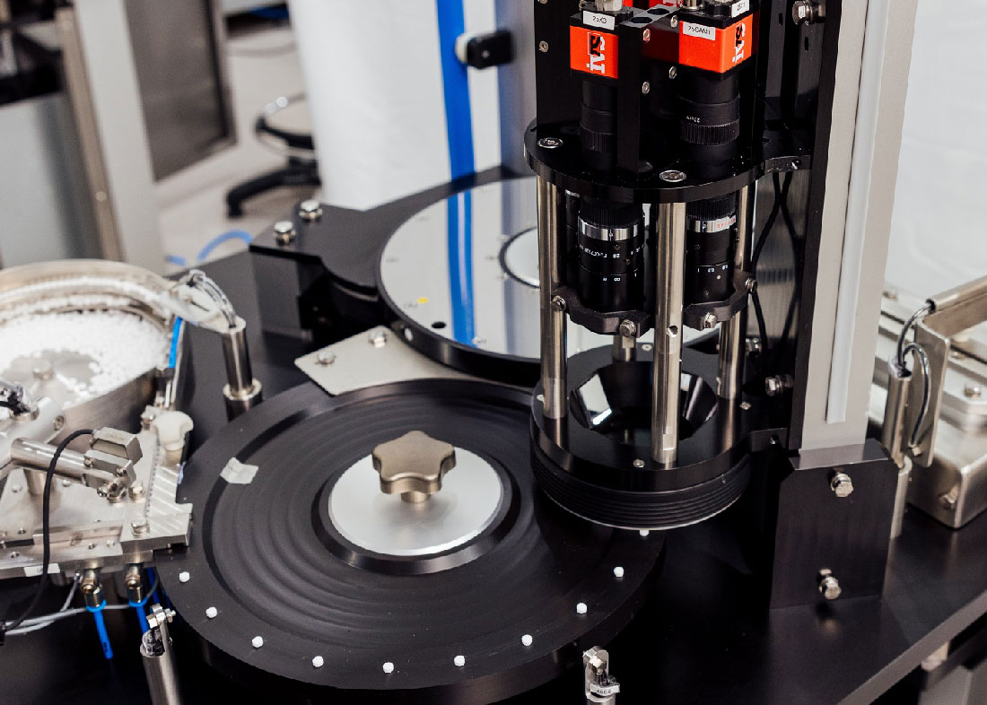
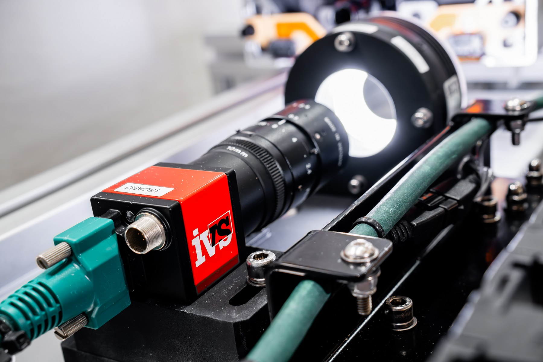
• High-speed industrial camera solutions with precision optics
• Edge, contour and label analysis to detect misalignment, damage, or missing items
• Lighting control to eliminate glare and shadows from complex packaging materials
• Modular station design adaptable to any point on the packaging line
• Audit-ready data collection with full traceability and image history
• User-friendly HMI for operators and QA teams
Why Choose Industrial Vision Systems (IVS)?
IVS is an internationally experienced machine vision provider, with a long track record in the medical, pharmaceutical, and life sciences sectors. Clients choose IVS for:
• Custom-built inspection systems tailored to exact product and line requirements
• Proven performance in validated and audited environments
• Comprehensive service from consultancy through to installation, validation and ongoing support
• Systems designed for real-world reliability, even under high-speed or multi-format production conditions
Final Thoughts: Vision Inspection as a New Standard
In a market where quality is paramount and compliance is critical, vision systems for medical devices are becoming a standard feature of well-run production lines. As demonstrated in this case, automated inspection not only reduces risk — it streamlines production, supports traceability, and ultimately ensures that only flawless products reach patients and healthcare providers.
If your business is still relying on human eyes for critical packaging checks, now is the time to explore how vision technology from IVS can raise your quality standards and future-proof your production.