In today’s increasingly automated manufacturing environments, machine vision is no longer just about reading barcodes or spotting product defects—it plays a critical role in precision in-line metrology. When properly implemented, in-line machine vision systems can deliver repeatable, accurate, non-contact measurements that significantly improve product quality and reduce inspection time. However, achieving this consistency and accuracy isn’t automatic—it requires careful consideration of imaging design, system calibration, and application-specific factors.
This article explores the key challenges and best practices for implementing repeatable and accurate machine vision metrology, with a focus on the practical realities of real-world factory floors.
Why Repeatability and Accuracy Matter in Machine Vision
In industrial settings, repeatability—the ability of a system to produce the same measurement result under consistent conditions—is often more valuable than pure accuracy. If a vision system produces consistent results, manufacturers can calibrate around any fixed bias and trust that in- and out-of-tolerance parts are reliably identified. That said, accuracy—how close a measured value is to the true value—still plays a vital role. The ideal metrology system combines high repeatability (precision) with high trueness, delivering results that are both reliable and close to the actual specification.
In high-volume, high-speed production environments, a failure in either can lead to:
- Increased scrap or rework
- Undetected defects reaching customers
- Regulatory compliance issues
- Wasted time and materials
More details on running a Gauge R & R study for machine vision can be found here.
The Unique Challenge of Non-Contact Measurement
Machine vision systems operate on non-contact principles, meaning they measure visible features of parts using cameras and light, rather than physically touching the parts as traditional gauges do. This fundamental difference introduces a range of practical challenges. For instance, consider a bore hole in a machined part. A manual caliper can measure the internal diameter at depth. However, a vision system can only assess the surface edges of the hole visible in the camera’s field of view. If the edges are chamfered, angled, or not perfectly flat, this surface-based measurement may not reflect the true inner dimension. The discrepancy between what is visible and what is intended must be understood and, where possible, corrected for. In many cases, if repeatability is high, engineers can apply known compensation factors to reconcile vision results with true dimensional targets.
Part Presentation: The Hidden Variable
One of the most critical and often overlooked contributors to measurement error in vision systems is part presentation—how the part is positioned relative to the camera and lighting system.
For example:
- A perfectly perpendicular bore hole will appear circular.
- A tilted part, even by a few degrees, will distort the bore into an elliptical shape, causing false readings.
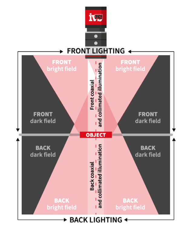
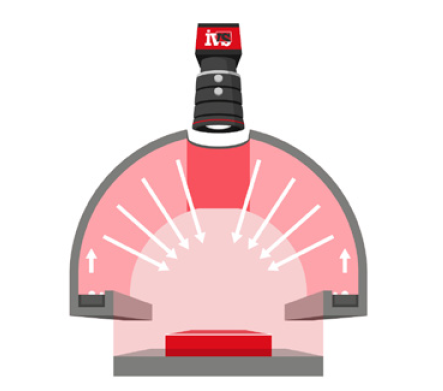
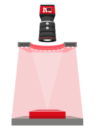
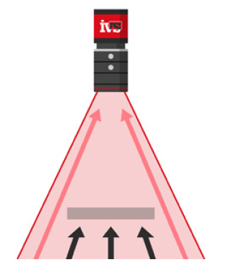
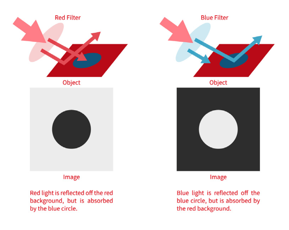
Lighting setups like backlighting, which highlight the silhouette of a part, are particularly sensitive to orientation. Telecentric lenses can reduce some of these effects, but they can’t eliminate all presentation-induced distortions.
To ensure repeatability, manufacturers must:
- Minimise variation in part positioning and orientation
- Use fixtures or robotic handling for consistent presentation
- Simulate and test worst-case misalignment scenarios
Understanding Measurement Metrics
Let’s explore three critical metrics that underpin repeatable and accurate measurements:
Precision (Repeatability):
- Describes how close measurements are to each other under unchanged conditions.
- Often expressed as standard deviation (SD)—a lower SD indicates higher precision.
- Critical for in-line systems that must classify parts as pass/fail consistently.
Trueness:
- How close the average measurement is to the actual value.
- Important for ensuring product conformity to specifications.
Accuracy:
- A combination of high precision and high trueness.
- While important, accuracy can often be adjusted post-measurement if precision is dependable.
Spatial Resolution: The Foundation of Precision
The resolution of your imaging setup directly determines the smallest detectable feature size. It’s calculated by dividing the field of view (FOV) by the number of pixels on the sensor. For example:
A 1000-pixel wide sensor covering a 25mm FOV yields a pixel resolution of 0.025mm/pixel.
But more importantly, gauge resolution—the smallest unit that can be reliably measured—should be at least 1/10th of the tolerance band. So for a ±0.1mm tolerance, a system must reliably resolve to 0.01mm.
This often results in surprisingly high-resolution requirements. Compromising here can render a system ineffective. Choosing the right sensor, lens, and lighting combination is essential for achieving the required resolution without sacrificing image quality.
Going Beyond Pixel-Level Precision: Sub-Pixel Algorithms
To improve resolution without simply increasing sensor size, many systems leverage sub-pixel measurement algorithms:
- Edge gradient analysis
- Regression fits (e.g., best-fit circles or lines)
- Shape connectivity analysis
These tools can achieve repeatability finer than one pixel—sometimes to 1/10th or even 1/20th of a pixel—but this comes with caveats. Sub-pixel claims must be empirically validated under real production conditions, not just assumed based on vendor specifications.
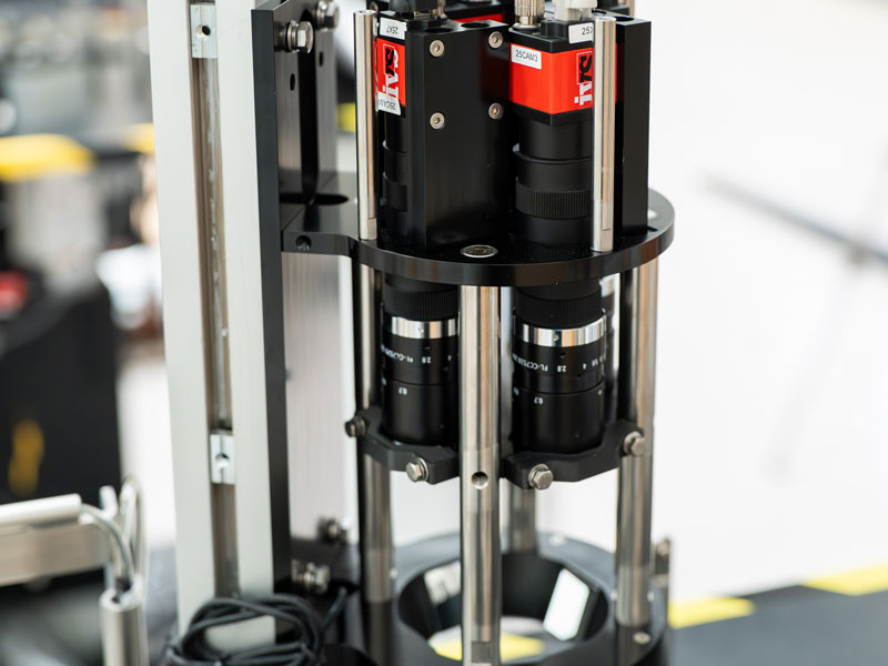
The Optics and Lighting Equation
You can’t achieve good measurements without a good image. That means selecting:
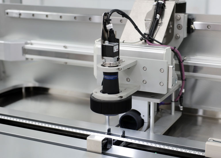
- High-quality lenses (often telecentric for metrology)
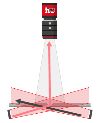
- Stable, directional lighting
- Mechanical isolation to reduce vibration
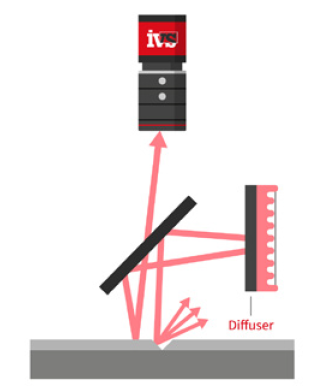
In larger FOV applications, maintaining uniform illumination becomes challenging. Shadows, reflections, and hot spots can reduce feature visibility and distort measurement edges. These distortions reduce repeatability even if the system is otherwise high resolution.
Consider testing:
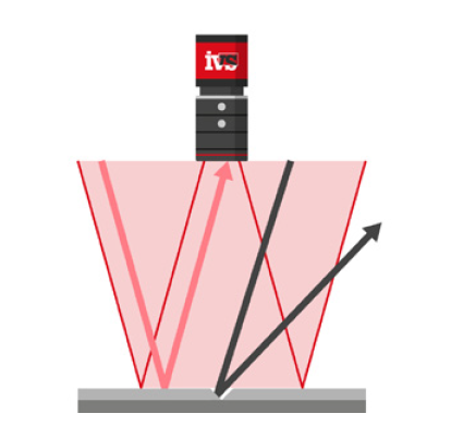
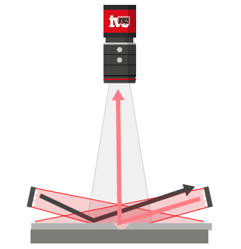
- Dark field lighting for edge enhancement
- Collimated or structured lighting for surface features
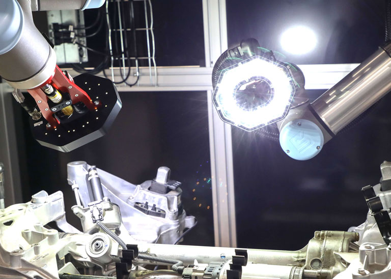
- Multiple camera angles if single-view systems can’t capture all required data
3D Vision: When 2D Isn’t Enough
For complex parts with depth variations, a 2D view is sometimes insufficient. This is where 3D imaging systems—such as structured light, stereo vision, or laser triangulation—shine. They provide depth information, enabling full dimensional inspection.
However, 3D systems come with their own implementation challenges:
- Higher data processing loads
- More complex calibration
- Increased sensitivity to surface finish
Still, for applications like automotive castings, gear inspection, or aerospace components, 3D systems may be the only way to achieve true spatial accuracy and repeatability.
Calibration: Turning Pixels into Real-World Measurements
Calibration transforms pixel-based measurements into real-world units (mm or microns) and is vital for traceability and compliance.
Benefits include:
- Real-world accuracy across different systems
- Compensation for perspective errors
- Multi-camera correlation
Regular re-calibration using certified calibration plates ensures long-term accuracy and helps identify when components drift or degrade over time.
Testing and Validation: Static vs. Dynamic Accuracy
Performance testing must go beyond lab trials. Two essential tests are:
- Static Testing: Measuring a part multiple times in a fixed position to assess core system repeatability.
- Dynamic Testing: Evaluating measurement variation during real production runs—this highlights error contributions from automation, vibration, lighting variation, or handling inconsistencies.
The dynamic error is usually higher than the static one and is the best predictor of actual system performance. If static performance is good but dynamic results are poor, focus on mechanical presentation improvements, not software tweaks.
Key Takeaways for Manufacturers
For manufacturers striving to meet tight tolerance requirements, boost productivity, and ensure regulatory compliance, investing in a well-designed, repeatable, and accurate machine vision metrology system is a smart move.
But success hinges on:
- Proper application-specific imaging design
- Understanding the limits of non-contact measurement
- Minimising part presentation variation
- Using high-quality components and validated software tools
- Performing rigorous testing, both static and dynamic
When approached methodically, machine vision metrology doesn’t just replace manual inspection—it transforms it, offering traceable, reliable measurement at production speed.
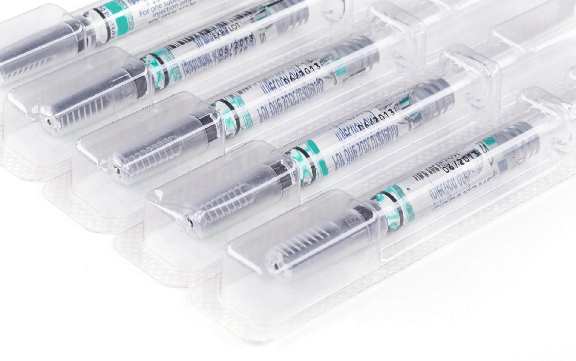
Want to Learn More?
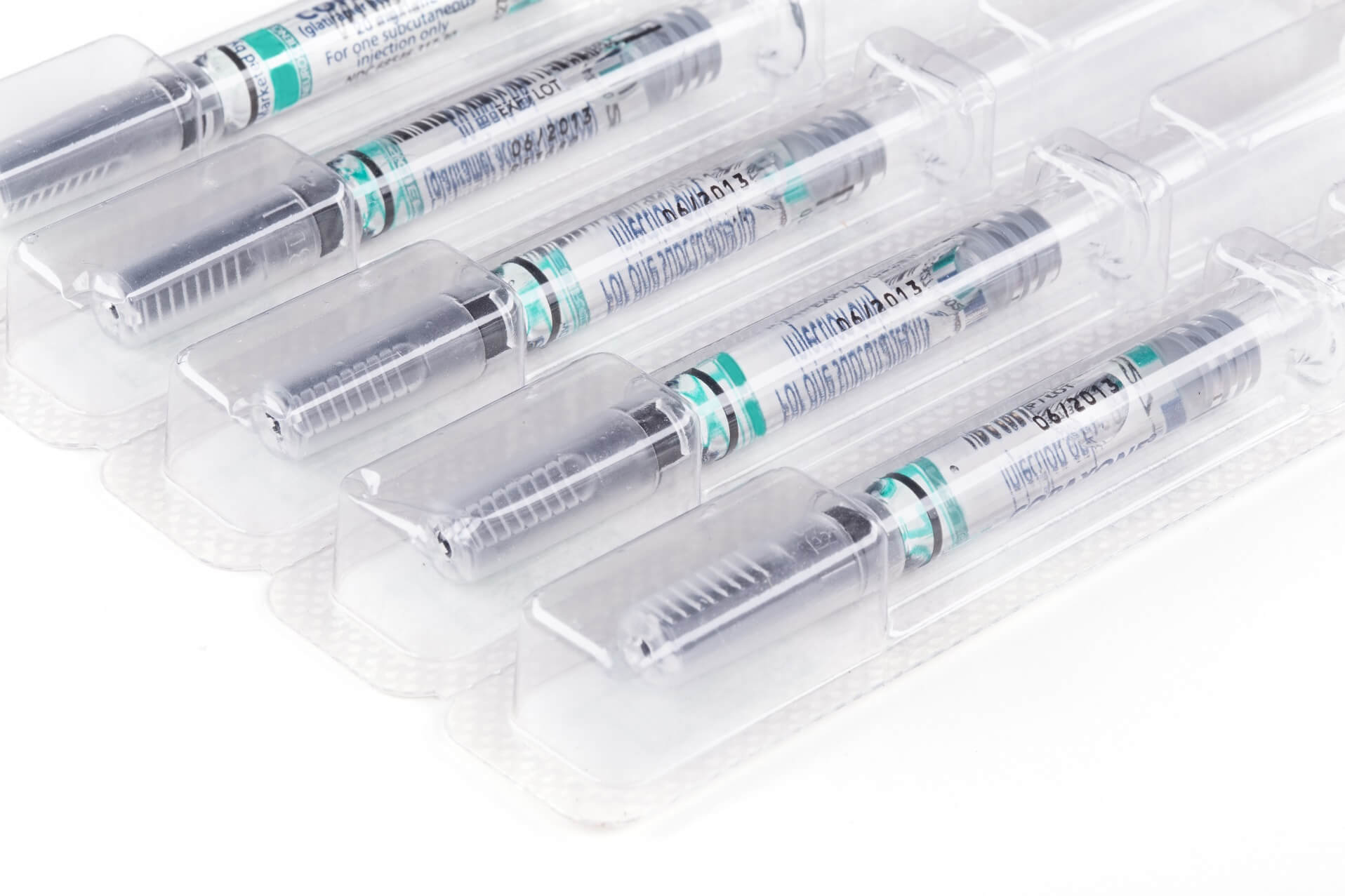
If you’re looking to improve your factory’s in-line measurement capabilities, speak with us. Whether it’s for medical device production, orthopaedic joints, automotive production or pharmaceutical manufacturing – repeatable machine vision metrology is within reach—with the right expertise.