How to calibrate optical metrology systems to ensure precise measurements

Optical metrology systems play a crucial role in various industries, enabling accurate and reliable measurements for quality control, inspection, and manufacturing processes. To ensure precise and consistent results, it is essential to calibrate these systems meticulously. By understanding the significance of calibration, considering key factors, and implementing regular calibration practices, organizations can optimise the performance of these systems. Accurate measurements obtained through properly calibrated optical metrology systems empower industries to maintain quality control, enhance efficiency, and drive continuous improvement.

How to calibrate your industrial vision system.

We’re often asked about the process for carrying out calibration on our automated vision inspection machines. After all, vision systems are based on pixels whose size is arbitrarily dependent on the sensor resolutions, fields-of-view and optical quality. It’s important that any measurements are validated and confirmed from shift-to-shift, day-to-day. Many vision inspection machines are replacing stand-alone slow probing metrology-based systems, or if it’s an in-line system, it will be performing multiple measurements on a device at high speed. Automating metrology measurement helps reduce cycle time and boost productivity in medical device manufacturing; therefore, accuracy and repeatability are critical.

In the realm of optical metrology, the utilisation of machine vision technology has brought about a transformative shift. However, to ensure that the results of the vision equipment have a meaning that everyone understands, the automated checks must be calibrated against recognised standards, facilitating compliance with industry regulations, certifications, and customer requirements.

The foundational science that instils confidence in the interpretation and accuracy of measurements is known as metrology. It encompasses all aspects of measurement, from meticulous planning and execution to meticulous record-keeping and evaluation, along with the computation of measurement uncertainties. The objectives of metrology extend beyond the mere execution of measurements; they encompass the establishment and maintenance of measurement standards, the development of innovative and efficient techniques, and the promotion of widespread recognition and acceptance of measurements.

For metrology measurements, we need a correlation between the pixels and the real-world environment. For those of you who want the technical detail, we’re going to dive down into the basis for the creation of individual pixels and how the base pixel data is created. In reality, the users of our vision systems need not know this level of technical detail, as the main aspect is the calibration process itself – so you can skip the next few paragraphs if you want to!

The camera sensor is split into individual pixels in machine vision. Each pixel represents a tiny light-sensitive region that, when exposed to light, creates an electric charge. When an image is acquired, the vision system captures the amount of charge produced at each pixel position and stores it in a memory array. A protocol is used to produce a uniform reference system for pixel positions. The top left corner of the picture is regarded the origin, and a coordinate system with the X-axis running horizontally across the rows of the sensor and the Y-axis running vertically down the columns is utilised.

The pixel positions inside the image may be described using the X and Y coordinates in this coordinate system. For example, the top left pixel is called (0,0), the pixel to its right is called (1,0), the pixel below it is called (0,1), and so on. This convention enables the image’s pixels to be referred to in a consistent and standardised manner. So this method provides a way (in combination with sub-pixel processing) to provide a standard reference coordinate position for a set of pixels combined to create an edge, feature or “blob”.

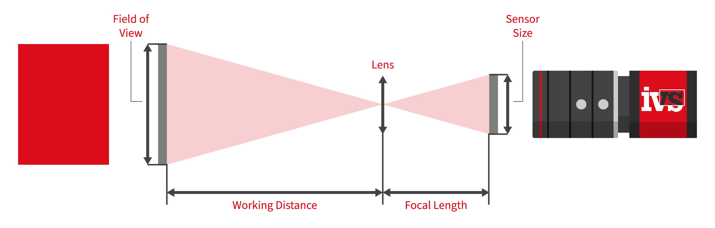
In machine vision, metrology calibration involves the mapping of the pixel coordinates of the vision system sensor back to real-world coordinates. This “mapping” ties the distances measured back to the real-world measurements, i.e., back to millimetres, microns or other defined measurement system. In the absence of a calibration, any edges, lines or points measured would all be relative to pixel measurements only. But quality engineers need real, tangible measurements to validate the production process – so all systems must be pre-calibrated to known measurements.

The process of calibration ensures traceability of measurements to recognised standards, facilitating compliance with industry regulations, certifications, and customer requirements. It enhances the credibility and trustworthiness of measurement data.

How do you calibrate the vision system in real-world applications?

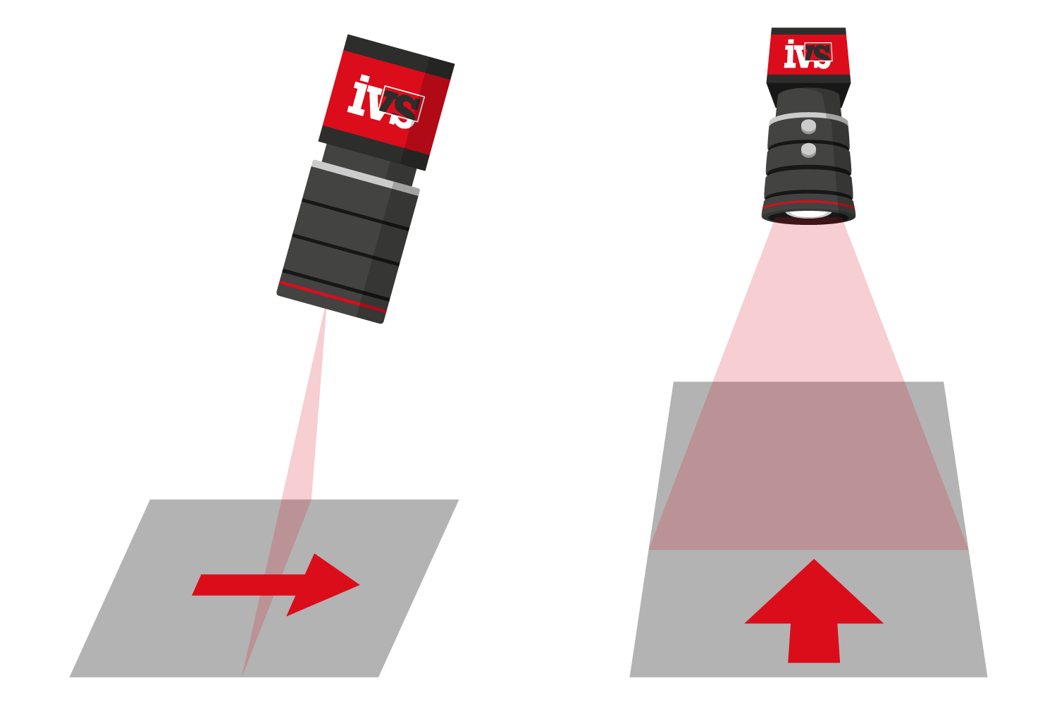
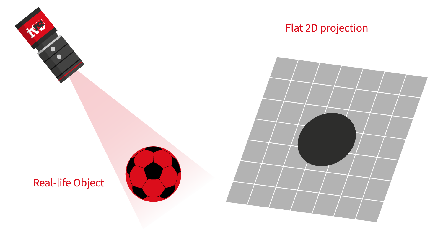
Utilising certified calibration artifacts or reference objects with known dimensions and properties is essential. These standards serve as benchmarks for system calibration, enabling the establishment of accurate measurement references. Proper calibration guarantees that measurements are free from systematic errors, ensuring the reliability and consistency of the data collected. The method of calibration will depend on if the system is a 2D or 3D vision system.

For a 2D vision system, common practice is to use slides with scales carved or printed on them, referred to as micrometre slides, stage graticules, and calibration slides. There is a diverse range of sizes, subdivision accuracy, and patterns of the scales. These slides are used to measure the calibration of vision systems. These calibration pieces are traceable back to national standards, which is key to calibrating the vision inspection machine effectively. A machined piece can also be used with traceability certification, this is convenient when you need a specific measurement to calibrate from for your vision metrology inspection.

One form of optical distortion is called linear perspective distortion. This type of distortion occurs when the optical axis is not perpendicular to the object being imaged. A chart can be used with a pre-defined pattern to compensate for this distortion through software. The calibration system does not compensate for spherical distortions and aberrations introduced by the lens, so this is something to be aware of.

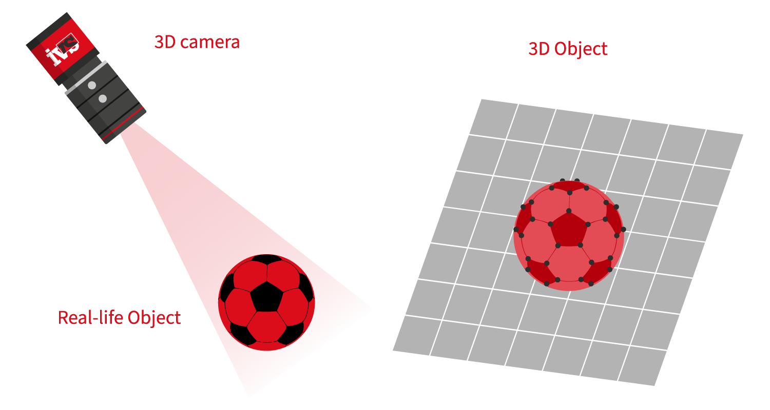
For 3D vision, you no longer need pricey bespoke artefacts or specifically prepared calibration sheets. Either the sensor is factory calibrated or a single round item in the shape of a sphere suffices. Calibrate and synchronise the vision sensor by sending calibrated component measurements to the IVS machine. You will instantly receive visible feedback that you may check and assess during the calibration process.

How often do I need to re-calibrate a vision system?

We often get asked this question, since optimal performance and accuracy of optical metrology systems can diminish over time due to factors like wear and tear or component degradation. Establishing a regular calibration schedule ensures consistent and reliable measurements. However, it’s often down to the application requirements, and the customer needs based on their validation procedures. This can take place once a shift, every two weeks, one a month or even once a year.

One final aspect is storage, all our vision inspection machines come with calibration storage built into the machine itself. It’s important to store the calibration piece carefully, use it as determined from the validation process, and keep it clean and free from dirt.

Overall, calibration is often automatic, and the user need never know this level of detail on how the calibration procedure operates. But it’s useful to have an understanding of the pixel to real-world data and to know that all systems are calibrated back to traceable national standards.

Clinical insight: 3 ways to minimise automated inspection errors in your medical device production line

Your vision system monitoring your production quality is finally validated and running 24/7, with the PQ behind you it’s time to relax. Or so you thought! It’s important that vision systems are not simply consigned to maintenance without an understanding of the potential automated inspection errors and what to look out for once your machine vision system is installed and running. These are three immediate ways to minimise inspection errors in your medical device, pharma or life science vision inspection solution.

1. Vision system light monitor.
As part of the installation of the vision system, most modern machine vision solutions in medical device manufacturing will have light controllers and the ability to compensate for any changes in the light degradation over time. Fading is a slow process but needs to be monitored. LEDs are made up of various materials such as semiconductors, substrates, encapsulants, and connectors. Over time, these materials can degrade, leading to reduced light output and colour shift. It’s important in a validated solution to understand these issues and have either an automated approach to the changing light condition through close loop control of grey level monitoring, or a manual assessment on a regular interval. It’s something to definitely keep an eye on.

2. Calibration pieces.
For a vision machines preforming automated metrology inspection the calibration is an important aspect. The calibration process will have been defined as part of the validation and production plan. Typically the calibration of a vision system will normally in the form of a calibrated slide with graticules, a datum sphere or a machined piece with traceability certification. Following from this would have been the MSA Type 1 Gauge Studies, this the starting point prior to a G R&R to determine the difference between an average set of measurements and a reference value (bias) of the vision system. Finally the system would be validated with the a Gauge R&R, which is an industry-standard methodology used to investigate the repeatability and reproducibility of the measurement system. So following this the calibration piece will be a critical part of the automated inspection calibration process. It’s important to store the calibration piece carefully, use it as determined from the validation process and keep it clean and free from debris. Make sure your calibration pieces are protected.

3. Preventative maintenance.
Vision system preventative maintenance is essential in the manufacturing of medical devices because it helps to ensure that the vision systems performs effectively over the intended lifespan. Medical devices are used to diagnose, treat, and monitor patients, and they play an important part in the delivery of healthcare. If these devices fail, malfunction, or are not properly calibrated, substantial consequences can occur, including patient damage, higher healthcare costs, and legal culpability for the manufacturer. Therefore, any automated machine vision system which is making a call on the quality of the product (at speed), must be maintained and checked regularly. Preventative maintenance of the vision systems involves inspecting, testing, cleaning, and calibrating the system on a regular basis, as well as replacing old or damaged parts.

Medical device makers benefit from implementing a preventative maintenance for the vision system in the following ways –
Continued reliability: Regular maintenance of the machine vision system can help identify and address potential issues before they become serious problems, reducing the risk of device failure and increasing device reliability.
Extend operational lifespan: Regular maintenance can help extend the lifespan of the vision system, reducing the need for costly repairs and replacements.
Ensure regulatory compliance: Medical device manufacturers are required to comply with strict regulatory standards (FDS, GAMP, ISPE) and regular maintenance is an important part of meeting these standards.

These three steps will ultimately help to lessen the exposure of the manufacture to production faults, and stop errors being introduced into the medical devices vision system production process. By reducing errors in the machine vision system the manufacturer can keep production running smoothly, increase yield and reduce downtime.

Why pharmaceutical label inspection using vision systems is adapting to the use of AI deep learning techniques

Automated inspection of pharmaceutical labels is a critical part of an automated production process in the pharmaceutical and medical device industries. The inspection process ensures that the correct labels are applied to the right products and that the labels contain relevant and validated information. These are generally a combination of Optical Character Recognition (OCR), Optical Character Verification (OCV), Print Quality Inspection and measurement of label positioning. Some manufacturers also require a cosmetic inspection of the label for debris, inclusions, smudges and marks. The use of vision inspection systems can significantly improve the efficiency and accuracy of the automation process, while also reducing the potential for human error.

Automated vision inspection systems can also help to ensure compliance with regulatory requirements for labelling, and provide manufacturers with a cost-effective and efficient way to improve the quality of their products. With increasing pressure to improve production efficiency and reduce costs, more and more pharmaceutical and medical device manufacturers are turning to automated vision inspection systems to improve their production processes and ensure quality products for their customers.

Over the last few years, more vision inspection systems for pharmaceutical label checks have been adapting to the use of deep learning and artificial intelligence neural networks, such as Convolutional Neural Networks (CNNs) or Recurrent Neural Networks (RNNs).

Using AI and deep learning for optical character recognition (OCR) can significantly improve the performance of automated inspection systems for pharmaceutical labels. Traditional OCR systems rely on pre-defined templates and rules to recognize and interpret text on labels, which can be limited in their ability to recognize text accurately in different fonts, sizes, and layouts.

AI-based OCR systems, such as those using deep learning, can be trained on a large dataset of labelled images, allowing them to learn and recognize different fonts, sizes, and layouts of text. This makes them more robust and accurate in recognizing text in real-world scenarios, where labels may have variations in their appearance. The deep learning machine vision systems can also be trained to recognize text that is partially obscured or distorted, which is a common problem in real-world scenarios. This allows the system to make educated guesses about the text, which can improve its accuracy and reliability.

On the flip side, while the level of recognition may improve for hard-to-recognise situations for traditional machine vision inspection, the system also must be validated to set criteria for FDA/GAMP validation. How can this be achieved for a neural deep learning system?

It is true that gathering data for training an AI-based vision inspection system can be a hassle, but it is a crucial step to ensure the system’s performance. One way to overcome this is by using synthetic, validated data, which can be generated using computer-generated images. This can reduce the need for natural images and allows a broader range of variations to be included in the dataset. These synthetic images could be tested and validated on a traditional machine vision set-up, before then transferred to the training set for the AI-based vision inspection. Another way is to use transfer learning, in which a pre-trained validated model is fine-tuned on a smaller dataset of images specific to the task. This can significantly reduce the amount of data and resources needed to train a new model.

In conclusion, validated industries such as medical devices and pharmaceuticals continue to adapt to new, robust methods for traceability and quality print checking. Deep learning is evolving to meet the unique validation requirements of these industries.

Your ultimate guide to GAMP validation for vision systems and industrial automation

You’re starting a new automation project, and vision inspection is a critical part of the production process. How do you allow for validation of the vision inspection systems and the machine vision hardware and software? This is a question we hear a lot, and in this post we’re going to drill down on the elements of validation in the context of vision systems for the medical devices and pharmaceutical industries. We’ll attempt to answer the questions by providing an overview of GAMP, a guide to key terminology and offering advice on implementing validation for your vision system and machine vision applications.

You’ll hear a lot of terminology and acronyms in industrial automation validation. So we’ll start by explaining some of the terms before drilling down on how the validation process works.

So what is GAMP? Good Automated Manufacturing Practice is abbreviated as “GAMP.” It’s a methodology for generating high-quality machinery based on a life cycle model and the concept of prospective validation. It was developed to serve the needs of the pharmaceutical industry’s suppliers and consumers and is part of any automation project. The current version of GAMP is GAMP 5. The full title is “A Risk-Based Approach to Compliant GxP Computerized Systems”.

The GAMP good practices were developed to meet the Food and Drug Administration’s (FDA) and other regulatory authorities’ (RAs’) rising requirements for computerised system compliance and validation in the industrial automation industry, and they are now employed globally by regulated enterprises and their suppliers.

GAMP was developed by experts in the pharmaceutical manufacturing sector, to aid in the reduction of grey areas in the interpretation of regulatory standards, leading to greater conformity, higher quality, more efficiency, and lower production costs. They tend to be methodological in nature, which in the context of machine vision matches the processes of industrial image processing.

So in layman’s terms, the GAMP and FDA validation is designed to prove the performance of a system in the fundamentals of what it is designed for and lays down the parameters and testing procedures to validate the process across the design, build, commissioning, test and production processes. In machine vision for industrial automation, this will be heavily biased towards the hardware and software specifications, along with the performance criteria for the vision system.

What is GxP that GAMP refers to? Simply, this refers to good practice, with the x in the middle referring to “various fields”. It refers to a set of guidelines and regulations that are followed in industries that produce pharmaceuticals, medical devices, and other products that have a direct impact on the health and well-being of people.

GxP guidelines and regulations are designed to ensure the quality, safety, and efficacy of medical device and pharma products. They cover various aspects of product development, manufacturing, testing, and distribution, as well as the training, qualifications, and conduct of the personnel involved in these processes.

GxP guidelines and regulations are enforced by regulatory agencies, such as the US Food and Drug Administration (FDA) and the European Medicines Agency (EMA), and non-compliance with these guidelines can result in fines, product recalls, and other legal consequences.
There are several different types of GxP, including:

  • GMP (Good Manufacturing Practice): This set of guidelines and regulations covers the manufacturing and testing of pharmaceuticals, medical devices, and other products. This is the most relevant to the validation of vision systems, inspection and machine vision in industrial automation.
  • GCP (Good Clinical Practice): This set of guidelines and regulations covers the conduct of clinical trials involving human subjects.
  • GLP (Good Laboratory Practice): This set of guidelines and regulations covers the conduct of laboratory studies involving the testing of chemicals, drugs, and other substances.
  • GPP (Good Pharmacy Practice): This set of guidelines and regulations covers the practice of pharmacy, including the dispensing and distribution of drugs and other products.

By following GxP guidelines and regulations and validation processes, companies can ensure that their products meet the highest standards of quality, safety, and efficacy, and that they are manufactured, tested, and distributed in a way that protects the health and well-being of their customers.

What is the ISPE? This is the “International Society for Pharmaceutical Engineering”. ISPE is an organisation that bridges pharmaceutical knowledge to improve the development, production, and distribution of high-quality medicines for patients around the world through such means as innovation in manufacturing and supply chain management, operational excellence, and insights into regulatory matters. The ISPE develops the GAMP framework, and GAMP 5 was developed by the ISPE GAMP Community of Practice (CoP).

So the above sets out the framework for validation and why it exists. We’ll now look at what processes are needed to fully validate a vision system into medical device and pharmaceutical manufacturing. On a high level the following critical steps are followed when validating a vision system in production:

1. Define the validation plan: This includes identifying the scope of the validation, the criteria that will be used to evaluate the system, and the testing that will be done to ensure that the system meets these criteria.

2. Install and configure the system: This includes setting up the hardware and software necessary for the system to function correctly, as well as configuring the system to meet the specific needs of the production process.

3. Test the system: This includes conducting functional tests to ensure that the system performs as intended, as well as performance and reliability tests to ensure that the system is accurate and reliable.

4. Validate the system: This includes verifying that the system meets all relevant regulatory standards and requirements, as well as any internal quality standards or guidelines.

5. Document the validation process: This includes documenting the testing that was done, the results of the tests, and any issues that were identified and corrected during the validation process.

6. Implement the system: This includes training production staff on how to use the system and integrating the system into the production process.

7. Monitor and maintain the system: This includes ongoing monitoring and maintenance of the system to ensure that it continues to function correctly and meets all relevant standards and requirements.

But each step needs to be broken down and understood in the context of the validation process relating to GAMP. The following lifecycle shows the typical steps required for the validation of the vision system in production.

What is a URS? A URS, or User Requirement Specification, is a document that outlines the requirements for a product, system, or service. It is typically created at the beginning of a project, and it serves as a roadmap for the development team, providing guidance on what the final product should look like and how it should function.

A URS typically includes a detailed description of the product’s intended use and user base, as well as the specific requirements that the product must meet in order to be successful. These requirements may include functional requirements (e.g., what the product should be able to do), performance requirements (e.g., how fast or accurately the product should operate), and quality requirements (e.g., how reliable or durable the product should be).

The URS is an important tool for defining and communicating the project’s scope and objectives, and it is often used as a reference document throughout the development process. It is typically reviewed and approved by stakeholders, including the development team, customers, and regulatory agencies, before the project begins.

In addition to serving as a guide for the development team, the URS can also be used to evaluate the final product to ensure that it meets all of the specified requirements. This process is known as “verification,” and it is an important step in the quality control process to ensure that the product is fit for its intended use.

The URS is the first document that is required for validation of the vision system (or other industrial automation system), it’s the base document which then leads on the FDS (Functional Design Specification) and the HDS (Hardware Design Specification) and the SDS (Software Design Specification) incorporated as part of that specification. These documents are typically provided by the vision system company as part of the scope of supply of a fully validated vision inspection solution.

What is an FDS? A Functional Design Specification (FDS) is a document that outlines the functional requirements of a product, system, or service. It describes the specific behaviors and capabilities that the machine vision inspection system should have in order to fulfill its intended purpose. The FDS typically includes a detailed description of the vision systems functional requirements, as well as any technical constraints or requirements that must be considered during the design and development of the inspection process.

The purpose of an FDS is to provide a clear and comprehensive understanding of the functional requirements of the overall inspection system, and to serve as a reference for the design and development team as you bring the product to life. It is an important tool for ensuring that the final vision system meets the needs and expectations of the end users.

An FDS may also include information on the vision user interface design, user experience design, and any other aspects of the product that are relevant to its functional requirements. It is typically developed early in the design process and is used to guide the development of the product throughout the project.

Prior to installation, the manufacturer will undertake a Factory Acceptance Test (FAT) which should be documented and agreed between the vision system supplier and the customer.

As the project progresses the applications team need to think about the three major milestones for test, commissioning and integration of the validated vision system – these include:

Installation Qualification (IQ) – this is the process used to verify that the vision system, equipment has been installed correctly and meets all relevant specifications and requirements. It is an important step in the validation process for ensuring that an inspection system is ready for use in a production environment.

During an IQ, a series of tests and checks are performed to ensure that the machine vision system has been installed properly and is functioning correctly. This may include verifying that all required components are present and properly connected, checking that all necessary documentation is complete and accurate, and verifying that the system or equipment meets all relevant safety and performance standards.

The purpose of IQ is to ensure that the vision system is ready for use and meets all necessary requirements before it is put into operation. It is typically performed by a team of qualified professionals from the customers side, and the results of the IQ are documented in a report that can be used to demonstrate that the system or equipment has been installed correctly and is ready for use.

Operational Qualification (OQ) – This is the process used to verify that the vision system complies with the URS and FDS. During an OQ, a series of tests and checks are performed to ensure that the system or equipment operates correctly and consistently under normal operating conditions. This may include verifying that the system or equipment performs all of its required functions correctly, that it operates within specified parameters, and that it is capable of handling normal production volumes.

Performance Qualification (PQ) – This is the final step and is performed by the final user of the vision system. It verifies the operation of the system under full operational conditions. It generally produces production batches using either a placebo or live product, dependent on the final device requirements.

All aspects of the validation approach are captured in the Validation Plan (VP), which, combined with the Requirement Traceability Matrix (RTM) remains live during the project’s life to track all documents and ensure compliance with the relevant standards and traceability of documentation.

Only after the completion of the Performance Qualification is the system validated, and ready for production use.

In summary. The process of validating a vision inspection system in an industrial automation system involves several steps to ensure that the system is accurate, reliable, and meets the specified requirements. These steps can be broadly divided into three categories: planning, execution, and evaluation.

Planning: Before beginning the validation process, it is important to carefully plan and prepare for the testing. This includes defining the scope of the validation, identifying the personnel who will be involved, and establishing the criteria that will be used to evaluate the system’s performance. It may also involve obtaining necessary approvals and documents, such as a validation plan or protocol.

Execution: During the execution phase, the vision inspection system is tested under a variety of conditions to ensure that it is functioning properly. This may include testing with different types of objects, lighting conditions, and image resolutions to simulate the range of conditions that the system will encounter in real-world use. The system’s performance is then evaluated using the criteria established in the planning phase.

Evaluation: After the testing is complete, the results of the validation process are analyzed and evaluated. This may involve comparing the vision system’s performance to the specified requirements and determining whether the system can meet those requirements. If the system fails to meet the requirements, it may be necessary to make modifications or adjustments to the system to improve its performance.

Throughout the validation process, it is important to maintain thorough documentation of all testing and evaluation activities according to GAMP 5 regulations. This documentation can be used to demonstrate the system’s performance to regulatory agencies or other stakeholders, and it can also be used as a reference for future maintenance or upgrades.

The process of validating a vision inspection system in an industrial automation system is a crucial step in ensuring that the system is accurate, reliable, and meets the specified requirements. By following a structured and thorough validation process, companies can ensure that their vision inspection systems are fit for their intended use and can help to improve the efficiency and quality of their operations.

Stop chasing shorts and flash in medical device mould production by using 100% vision inspection

This month we look at the problem of flash and shorts in injection moulded medical device products and what the benefits are of automating an inspection process for flash and short detection. Medical devices are generally made up of an assembly of smaller plastic components, which together form an assembly. This could be part of a syringe system, testing kit, injection pen, sterile pack, caps, inserts, tubes, inhaler and medical tool holders – or a large assembly, such as breathing apparatus, medical machinery or diagnostic kits. Whatever the assembly or medical kit, the tolerances and fit of the medical device are normally of utmost importance, especially as most devices will be filled with a pharmaceutical drug of some kind or be used in a clinical setting. Flash and shorts could cause leakages, changes to the operation of the device, assembly faults or simply look bad to the user. Flashes and shorts in medical device components need to be rejected before they have a chance of reaching the end-user or the pharmaceutical supplier.

There are many things that can cause flash in plastic injection mouldings, such as mismatched parting lines, bad venting, low clamping pressure, low viscosity, and uneven flow. Some of these problems are caused by the tools, while others are caused by how the tools are used in the moulding machine.

Parting Lines that are mismatched: Dust, dirt, contaminants, and leftovers can make it hard for the two halves of an injection mould to fit together properly. If the holes in the mould are worn, they won’t fit together as well either. The metal surfaces of mould plates can also be deformed by pressure, and complicated part shapes can make it hard to close the mould.

Wrong Venting: Vents that are too big or too small can let out too much or too little air, depending on how old and worn they are. If the vents aren’t deep enough, stiff plastics may be able to stick out, and if the vents aren’t thin enough, fluids may be able to pass through.

Low Clamping Pressure: During injection moulding, the pack/hold phase makes sure that the cavity is completely filled, but it can also force the mould open. Even if the mould halves fit together tightly, plastic could leak out of the mould if the clamping pressure isn’t strong enough to stop this force.

Low viscosity and uneven flow: Depending on how the plastic is processed, it may flow too easily or fill the mould too quickly. For example, melt temperatures that are too high, residence times that are too long, moisture left over from drying that wasn’t done well enough, and using too many coolants.

Shorts, also called “short shots,” are parts that aren’t filled with enough plastic and often don’t have any details because of this. Sinks and parts that aren’t packed tightly enough can sometimes be caused by shorts or be a sign that shorts are starting. There are many things that can cause shorts, and it is important to figure out what they are before trying to fix them. A common cause is that the venting isn’t set up right, so gases can’t escape and plastic can’t flow into the cavity. Another common cause is that the non-return valve on the screw isn’t closing properly, which lets plastic flow backwards as the machine injects.

Many of the actions taken to eliminate flash can result in shorts and vice versa. These actions can be made via changes to the process, mould, or combination of the two. Whatever the solution to eliminate flash and shorts, there’s always the possibility they will be introduced into the product at a later date, and so 100% automated inspection of flash and shorts for medical devices is a perfect solution to stop bad products from getting into the market.

So you have your machine set and production running, but many process engineers end up chasing the process and firefighting the moulding processing, and so moving the goalposts between shorts and flash if the process starts to go out of sync. Using automated inspection can help control this problem and reduce the chase! The vision inspection systems can be interfaced directly with the Injection Moulding Machine (IMM), with products falling out of the tooling on the outfeed conveyor, which in turn can be the in-feed conveyor for a vision inspection machine.

Vision inspection of mould defects is achieved by moving the product either directly into a bowl feed for movement passed the cameras or via using a cleated belt conveyor, allowing the IMM robot to deliver the product to pockets which the vision system robot can pick and introduce into the inspection machine.

Vision systems for flash and short detection can find and measure the fault size, and even the XY location of the flash on the part, allowing statistical process control data of the medical device flash and short position to be logged, allowing process engineering to investigate the root cause of the problem. And remember, it is also possible to check for other defects during the inspection process, so if weld lines, chips, cracks, particulates or distortions are also an issue with the process, these can be incorporated into the automated inspection process. Automated inspection should form part of the validated process for medical device production.

The vision system allows 100% inspection of every moulded product, giving reassurance that the final product delivered to the customer is of the correct quality level, will fit, and won’t cause a leak! This allows you to stop the chase, knowing your flash and shorts will be automatically sorted and rejected at source.

How to use semi-automatic inspection of pharmaceutical vials and syringes for regulatory compliance.

Semi-automatic (or Semi-automated) inspection machines for the pharmaceutical industry are intended for easy and effective examination of vials, ampoules, cartridges, and syringes carrying injectable liquids, powders, or freeze-dried products. This is the step up from a manual inspection approach which would typically be done by a trained inspector by rotating the vial in front of a black and white background for the analyses of certain defects, particles and particulates. The semi-automatic approach allows for higher volumes of pharmaceutical products to be inspected at greater speeds.

In simple terms, “Semi-Automatic” means the ability to rotate the product and present it with the correct lighting LUX level on a black and white background for the purpose of an operator to visually identify defects in the container or contents. This is typically in the form of a stand-alone semi-automated machine or part of an in-feed or in-line production system. Therefore, this shouldn’t be confused with fully automated visual inspection systems.

The key documents relating to the inspection of pharmaceutical vials and ampoules for contamination are driven by the United States Pharmacopeia (USP) Chapter 1 Injections and Implanted Drug Products (Parenterals). Product Quality Tests states that injectable drug preparations should be designed to exclude particulate matter as defined in USP Chapters “787” Subvisible Particulate Matter in Therapeutic Protein Injections, “788” Particulate Matter in Injections, and “789” Particulate Matter in Ophthalmic Solutions. Each final container should be inspected for particulate matter, as defined in Chapter “790” Visible Particulates in Injections. Containers that show the presence of visible particulates must be rejected.

Particulates can take all forms, from contamination and debris particulates, coating fragments, air bubbles or inconsistencies, visual defects in primary containers, polymer particles through to glass & metallic particles and microscopic cracks or inclusions in the glass or polymer. All these levels of defects need to be identified and rejected.

Every product needs to undergo a visual inspection to determine whether or not it contains any particle matter. It is possible to automate, manually perform, or partially automate the initial 100% check. The subsequent inspection to ensure that the acceptable quality level (AQL) has been met must be carried out manually. The presumed value for the lower limit of the visible range is 100µm; however, this value can shift based on the product container, the nature of the drug product, and the qualities of the particulate matter (shape, colour, refractive index etc.).

The sample in its primary container (vial, prefilled syringe, and glass cartridge) is rotated under standardised conditions for semi-automated visual inspection (roughly above 50-100 µm). The liquid in the spinning and/or subsequently stopped container can then be viewed to confirm compliance to quality levels. This is the way to reach regulatory compliance by applying semi-automatic inspection.

Although the regulation of particulate matter in pharmaceutical products is as detailed above, there is no regulatory guidance on either the limits of particulate matter in principal packaging components. Instead, the specifications are determined through collaboration between the customers and the providers. To lessen the amount of particulate matter in finished drug products, pharmaceutical manufacturers and packaging suppliers must work together to achieve this goal. In particular, this can be accomplished by making use of components that have minimal levels of loose, embedded, and adhered particulates. But no matter what contingencies are put in place, the production process should include a level of semi-automatic inspection to allow rouge particulates to be rejected from the final product.

Human inspectors are adaptable and can provide a response to something they have never seen before or something that “doesn’t look right”. They are also able to more easily withstand typical variations in containers, particularly those generated by moulding, which results in a reduction in the frequency of wrongly rejected good products. This compares to fully automated visual inspection, which has rigid boundaries for a pass and fails. However, people are restricted in the number of inspections that can be performed (i.e., the number of containers per minute or hour that they can inspect). Therefore, semi-automatic inspection is the solution to allow a high volume of product to be inspected at speed by an operator while still complying with the relevant regulatory levels.

Operators are also prone to weariness and require numerous pauses in order to work at a high level for extended periods of time. All of these constraints contribute to a greater degree of variation in the outcomes of manual inspections; however, this variation can be reduced by semi-automated inspection, combined with receiving enough training and adhering to standard operating procedures.

Manufacturers should conduct a 100% inspection during the stage at which there is the greatest likelihood that visible particulates will be detected in the final container (for example, before labelling to maximise container clarity). This is the stage at which the likelihood that visible particulates will be detected in the final container is highest. The equipment and the physical environment in which the visual inspection will be performed should both be designed by the manufacturers to reduce the amount of unpredictability in the inspection process while simultaneously increasing the amount of information that can be gleaned from it.

After 100% semi-automated inspection is completed, a manual inspection based on ISO 2859-1/ANSI/ASQ Z1.4 should be performed. The size of the AQL sampling depends on the batch size. Inspection Level II should be used.

Overall, Semi-automatic inspection of pharmaceutical products provides a route to regulatory compliance prior to the adoption of fully automated visual quality control.

3 simple steps to improve your machine vision system

What’s the secret to a perfect vision system installation? That’s what all industrial automation and process control engineers want to know. The engineering and quality managers have identified a critical process requiring automated inspection, so how do you guarantee that the machine vision system has been set up to the best possible engineering standard. And how can you apply this knowledge to refine the current vision systems on the line? Let’s look at some of the critical parts of the vision inspection chain and see the vital elements and what needs to be addressed. IVS has been commissioning machine vision systems for over two decades, so we understand the core elements inside and out of vision system installs. Use some of our tricks of the trade to improve your vision system. These 3 simple steps to improve your machine vision system will help you understand the immediate changes you can make to improve a vision system.

Step 1 -Lighting and filters.
What wavelength of light are you using, and how does this compare to the sensitivity of the camera, coupled with the colours on the part requiring inspection? An intelligent approach to how segmentation of the scene will take place should be based on the correct lighting set-up, the angle of the machine vision lighting and how the contrast is created based on the colour of the part against the light, either reflecting to or away from the camera. Coloured illumination may intensify or suppress defined colours in monochrome imaging. This way, the contrast helps recognise relevant features, which is decisive for an application-specific and optimally matched vision solution. For example, blue light cast onto a multi-colour surface will only be reflected by the blue content. The more blue content in the object, the more light is reflected, so the brighter the object will appear. In contrast, red content illuminated in blue appears exceptionally dark.

Combining, a filter mounted on the end of the lens allows blocking all unwanted ambient light and passing only the necessary wavelength of light required, increasing contrast and resolution. The choice of which filter to use depends on the type of result you are trying to achieve. But selecting an appropriate filter may improve your current system’s quality if ambient light is a problem for you.

Bandpass filters are frequently one of the simplest methods to significantly improve image quality. They have a Gaussian transmission curve and are ideal for investigating the effects of monochromatic imaging. But what are the different filters available?

Multi Bandpass Filters
Multi-Bandpass Filters use a single filter to transmit two or more distinct wavelength bands. They provide natural colour reproduction during the day and near-infrared illumination at night, resulting in accurate, high-contrast pictures. As a result, these are more suited for applications including intelligent traffic solutions, security monitoring, and agricultural inspection.

Longpass Filters
Longpass Filters enable a smooth transition from reflection to transmission and are available in various wavelengths based on the system’s requirements. Longpass filters are an efficient method for blocking excitation light in fluorescent applications and are best employed in a controlled environment where several wavelengths must be passed.

Shortpass/NIR Cut Filters
Shortpass filters offer an unrivalled shift from transmission to reflection and superb contrast. They work best in colour imaging to ensure natural colour reproduction and prevent infrared saturation.

Polarising Filters
Polarising filters minimise reflection, increase contrast, and discover flaws in transparent materials. They’re ideally suited for tasks requiring a lot of reflection, such as analysing items on glossy or very shiny surfaces.

Neutral Density Filters
Neutral Density Filters are known in the machine vision industry as “sunglasses for your system” because they diminish light saturation. Absorptive and reflective styles are available and are ideally suited for situations with excessive light. They offer excellent methods for controlling lens aperture and improving field depth.

So how do you match the filter to the light? Well, the LED’s nanometers (nm) wavelength typically relates to the band pass rating for the filter. So if you work in UV at 365 or 395nm, you would use an equivalent rated filter – BP365. If you’re using a green LED at 520nm, this would be a 520 band pass filter, and so forth. According to the filter rating, most filters have a curve chart to see where the light is cut-off.

Step 2 Camera resolution and fields of view (fov)
A vision system’s spatial resolution refers to the sensor’s active available pixels. When reviewing an improvement in your set-up and understanding where the fault may lie, it’s important to consider how many pixels you have available for image processing relative to the size of the defect or computation you are trying to achieve. For example, if you are trying to defect a 100 micron (0.1mm) x 100 microns (0.1mm) inclusion on the surface of a product, but the surface is 4m x 4m in size, by using a standard 5MP camera (say 2456 x 2054 pixels) you will only be able to resolve a single pixel to at best 4000/2054 ~ so 1.9mm. This is nowhere near the level of detail you need for your imaging system. So to improve your machine vision system, see what size of a defect you need to see and then work out your field of view (fov) relative to the pixels available. But bear in mind having a single-pixel resolution for your measurement is not good enough, as the system will fail the Measurement Systems Analysis (MSA) and Gauge R&R studies (These are tests used to determine the accuracy of measurements).

In this case, you need to be at a minimum of 20 pixels across the measurement tolerance – so 0.2/20 = 0.01mm. Therefore, you will need 10 microns per pixel for accurate, repeatable measurement – over 4m; this is 400,000 pixels. So the 5MP pixel camera original specified will never inspect one shot – the camera or the object will have to be moved in small fields of view or larger resolution cameras specified for the system to hit the inspection criteria.

Step 3 Vision algorithm optimisation
One of the major steps for improving a machine vision system is a thorough review of the vision system software and the underlying sequence of inspection for the image processing system. If the system is a simple, intelligent vision sensor, it might be a matter of reviewing the way the logical flow of the system has been set. Still, for more complex PC-based vision applications, there will be some fundamental areas which can be reviewed and checked.

1. Thresholding. Thresholding is a simple look-up table that places pixel levels into a binary 1 and 0 depending on where they sit above, below or in-between two levels. The resulting image is a pure black and white image, then used to segment an area from the background from another object. Dynamic thresholding is also available, which intuitively sets the threshold level based on the pixel value distribution. But because it uses the fundamental pixel grey level to determine the segmentation, it can be easily affected by changes in light, as this will ultimately change the pixel value and lead to changes required to the threshold level. This is one of the most common faults in a system which has not been set up with a controlled lighting level. So if you are reviewing a threshold level change, you should also check the lighting and filters used on the system, as seen in Step 1.

2. Calibration. Perhaps not calibration in the true sense of the word, but if the camera on your vision system has been knocked out of place (even slightly), it may have detrimental effects on the inspection outcome and the yields of the vision system. Re-calibration may need to be done. This could initially be checked, as most modern systems have a cross-hair type target built into the software to allow a comparison image from the original system install to be compared with a live image. Check the camera is in-line, and the field of view is still the same. Focus and light should also be consistent. Some measurement-based machine vision systems will come shipped with a calibration piece or a Dot and Square Calibration Target. These generally come with a NIST Traceability Certificate, so you know that the artefact is traceable to national standards. This calibration target should be placed, and the system checked against it.

So these 3 simple steps to improve your machine vision system may just help you increase your vision system’s yield and stop the engineering manager from breathing down your neck. This will ultimately enhance your production productivity and advance the systems in use. And remember, you should always look at ways to reduce false failures in a vision system; this is another way to boost your vision system performance and improve yield.

How to automate Critical to Quality (CTQ) metrology checks

You spend your days loading and unloading parts into the CMM and checking every dimension on the part. In orthopaedic joint and medical device manufacturing, this can be a time-consuming and sometimes necessary requirement for validated processes. Increasingly, though, manufacturers are looking at what the true value is to this, and if they should be inspecting only for the Critical to Quality (CTQ) dimensions, rather than 100% inspection of every dimension. This reduces the time needed for inspection, decreases the need for a costly individual CMM’s, and allows for multiple parts to be inspected on a single fixture at speed.

What is Critical to Quality?
Critical to quality (CTQ) is the quality of a product or service in the eyes of the voice of the customer (VOC). It is a useful to identify the critical to quality parameters as they relate to what is important to the customer overall. In general, the two most important factors are the very specific end-product parameters and the associated process parameters that determine the quality of the end-product. Once these parameters are identified, the quality department will want to monitor, control and continuously improve upon these CTQ parameters, but not necessarily every dimension on the product. Businesses may better understand and meet consumer wants and expectations – as well as improve the product quality and service they provide – by listening to the voice of the customer. To promote customer satisfaction and loyalty, these VOC programs recognise and respond to the voice of the consumer. Ultimately, the VOC leads down to the CTQ requirements in manufacturing.

Automating metrology inspection
CTQ dimensions can be specifically singled out, and vision metrology applied for automatic measurement and evaluation of components, rather than the traditional CMM route. Measurement programs for both roughness measurement and form measurement can be automated quickly and easily with vision systems. Vision inspection enables the automatic and user-independent measurement of micro-precision parts or smallest component features on large surfaces. Measurement of shape (distances, shape deviation, positional relationships…) and roughness parameters as well as of cutting edge parameters (radius, contour, angle…). This allows multiple nested products to be inspected at speed compared to the single CMM inspection route, allowing higher throughput and releasing engineers from the costly time for mounting and demounting products from a CMM. Machine vision measuring is used to autonomously confirm the dimensional accuracy of components, parts, and sub-assemblies without the need for operator intervention. Machine vision has the advantage of being non-contact, which means it does not contaminate or damage the part being inspected.

Factory information interfaces enable networking and communication with existing production and quality management systems according to the smart manufacturing production concept, thus all data and traceability is immediately available to engineering and quality. Allowing trends and spikes in quality to be seen quicker.

So in the future, don’t continue to mount a single product in a CMM and check products one by one – drill down on the CTQ and the VOC, and automate your metrology checks using automated vision inspection instead – to increase throughput, reduce overhead and ultimately be more productive.

The best way to check your return on investment when implementing machine vision.

We’ve looked previously at the operational benefits of using machine vision but today we’re going to drill down on the economic benefits and how they fit in the payback you can expect from installing an automated visual inspection machine or system.

The economic case for investing in machine vision systems is usually strong due to the two key following areas:

  1. Cost savings through reducing labour, re-work/testing, removing more expensive capital expenditure, material and packaging costs and removing waste
  2. Increased productivity through process improvements, greater flexibility, increased volume of parts produced, less downtime, errors and rejections

However, just viewing the benefits from an economic perspective does not do justice to the true value of your investment. Machine vision systems can add value in all of the additional following ways. Unfortunately, due to the intangible nature of some of these contributors it can be difficult to put an actual figure on the value but that shouldn’t stop attempts to include them. These five pillars of payback are critical in understanding the economic benefits of installing vision systems and are the best way to assess how machine vision can impact your organisations bottom line.

Intellectually

  • By freeing staff from repetitive, boring tasks they are able to focus thinking in ways that add more value and contribute to increasing innovation. This is good for mental health and good for the business.
  • By reducing customer complaints, product recalls and potential fines automated inspection can help to build and protect your brand image in the minds of customers
  • Building a strong image in the minds of potential business customers through demonstrating adoption of the latest technology, particularly when they come and visit your factory!
  • Through the collection of better data and improved tracking machine vision can help you develop a deeper understanding of your processes

Physically

  • The adoption of machine vision can help to complement and even improve health and safety practice
  • Removing operators from hazardous environments or strenuous activity reduces exposure to sickness, absence, healthcare costs or insurance claims

Culturally

  • Machine vision can contribute and even accelerate a culture of continuous improvement and lean manufacturing
  • Through increased competitiveness and improving service levels machine vision helps build a business your people can be proud of

Environmentally

  • Contributing to a positive, safe working environment for staff
  • Through better use of energy and resources, smoother material flow and reduced waste machine vision systems can help reduce your impact on the environment

The costs
Costs can range from several hundred pounds for smart sensors and cameras, up to hundreds of thousands of pounds for complex IVS automated inspection machines. Of course, this will depend on the size and scope of your operations and specification – and may be more or less.

However, even in the case of high levels of capital investment it should be obvious, from the potential benefits outlined above, that a machine vision system can quickly pay for itself.

How to choose a camera for a machine vision application

For the new year we thought it would be useful to go back to basics, to understand how to choose the correct camera for a machine vision application. With ever increasing options we want to drill down on the choices available and to understand why we use certain IVS cameras in our machines.

A camera’s ability to capture a correctly-illuminated image of the inspected object depends on the direct relationship between the sensor and the lens. The sensors job is to convert light (photons) from the lens into electrical signals (electrons). Typically, it will do this using either charge coupled device (CCD) or complementary metal oxide semiconductor (CMOS) technology which digitize the electrons into an image consisting of pixels. The image can then be sent to the processor for analysis. Low light creates dark pixels and bright light creates brighter pixels.

Parameters such as part size and inspection tolerances will help inform the required sensor resolution and it’s very important to ensure the right one is chosen for the required application. Higher degrees of accuracy in measurement will require higher levels of sensor resolution.

Depending on application requirements machine vision systems often consist of a number of cameras. These can be monochrome and/or colour, and capture, interpret and signal with the control system to deliver the required solution.

Line Scan (1D sensors)

Line scan cameras collect single lines of images and are typically used for inspecting moving objects which are transported past the camera. They can also be useful for moving, very large objects or cylindrical objects which can be rotated. Where colour information is important this can also be achieved with line scan cameras.

Since the camera is only capturing one line it can come with certain limitations. For example, illumination needs to be extremely precise and because the camera aperture needs to remain open most of the time, reducing the depth of field, it can make capturing objects at different distances more problematic.

Area Scan (2D sensors)

In area scan cameras the sensor has a large matrix of image pixels generating a two-dimensional image in one exposure cycle. Because area scan cameras are capturing a rectangular area it is typically easier to install high performance lighting with this set-up as opposed to line scan cameras.

How to choose a camera for a machine vision application.

Area scan cameras also make it possible to take short exposure images using strobe lighting that brings a lot of light to the sensor in a short period of time. As such area scan cameras are used in the majority of applications for image acquisition.

2D & 3D Imaging

3D machine vision helps to overcome complex, high accuracy, real-time challenges where the practical limitations of 2D vision means it simply can’t be used. In particular 2D Vision is limited in applications where:
● shape information is critical to performing a task
● there is sensitivity to lighting issues
● it is difficult to achieve high contrast levels
● object movement may impair image accuracy
● imaging three-dimensional shape, form or volume is a necessity
Of course, for many simple applications these issues are of no consequence and therefore 2D vision, using either line scan or area scan cameras, is perfectly acceptable.

How to choose a camera for a machine vision application.

However, 3D imaging is growing in importance within the machine vision industry. As outlined in previous posts, although it is more time, processor and software intensive, rapid advances in technology, algorithms and software mean that these systems are now more than capable of keeping up with production line throughput requirements.

How to choose a camera for a machine vision application.

Because they capture extra third dimension data reliably, 3D machine vision systems are immune to the aspects of lighting, contrast, and distance to object suffered by their 2D counterparts.

As such some of the key applications of 3D imaging include:
● Measurement of volume, height, thickness, holes, curves and angles
● Robot guidance, bin picking for placing, packing or assembly
● Quality control where 3D CAD models have been used
● Where understanding of 3D space and dimensions is required
● Inspecting low contrast objects

There are four separate commonly used methods for 3D imaging:
1. Scanning based triangulation describes the angular relationship between the object being scanned, the laser and the camera. The approach involves the projection of a laser onto the surface of an object which is then viewed by the camera from a different measured angle. Any deviations of the line represent shape variations and lines from multiple scans can be assembled into a depth map or point cloud, representing the 3D image. Often multiple cameras are used, tracking laser lines from different angles and then merging data sets into a single profile. This helps to overcome any issues with ‘shadowing’ a situation where a single laser line is blocked from passing through parts of an object, by other parts of the same object.
2. Stereo vision, as the name suggests, is based on using two cameras, much the same as a pair of human eyes. Using the triangulation technique the two captured 2D images are then used to calculate a 3D image.
3. Time of flight 3D cameras measure the time which a light pulse takes to reach the object and return for each image point. As a result they have limitations in respect to the distance they can be used from an object and resolution meaning they are only suitable for specific applications.
4. Structured light uses sophisticated light techniques to create structured patterns that encodes 3D information direct to the camera scene.

How to choose a camera for a machine vision application.

Whatever the task, it’s important to understand how all the elements of the machine vision system interact to create a robust and reliable solution. Starting with the camera is the best approach, and building up the system architecture around it.

11 ways machine vision is used in electric vehicle battery production

Here at IVS our vision system solutions are utilised for the inspection of electric vehicle battery production. We thought it would be interesting in this post to drill down a little more of how machine vision is used in this fast-developing industry sector.

How are electric vehicle batteries made?

Carbon or graphite, a metal oxide, and lithium salt are all used to make lithium-ion batteries for electric vehicles. Positive and negative electrodes are made up of these elements, which when mixed with electrolyte form an electric current that allows the battery to work to power a car. It’s also the same type of battery that’s used in common devices like cell phones and computers, but on a far larger scale.

The materials used to make EV batteries come from many different countries and sources. Subterranean ponds are the most common source of lithium. The ponds liquid is drained out and left to dry in the sun. The Andes Mountains, which span through Chile, Argentina, and Bolivia, provides a large portion of the lithium used in electric car batteries. There are additional rock-mined deposits in China and the United States. The cobalt used in electric vehicle battery production mostly comes from mines in the Democratic Republic of Congo. Nickel is largely gathered in Indonesia and the Philippines. Lithium is converted to lithium carbonate, which is subsequently processed at a battery plant. The batteries are assembled at the production factory and then installed in an electric vehicle with zero emissions.

EV’s employ a pack, which is made up of thousands of separate Li-ion cells that work together, rather than a single battery like a phone. Electricity is utilised to make chemical changes inside the car’s batteries while it is charging. These adjustments are reversed when it’s on the road to generate electricity.

So how is machine vision used in a battery plant?

Machine vision is used in the complete electric vehicle (ev) manufacturing cycle, providing quality and consistency to the production across all areas. But getting the quality right on battery production for electric vehicles is critical for safety, life cycle and achieving greater energy density – and to prevent degradation and to minimise waste. Therefore, machine vision provides the eyes on quality in electrical vehicle manufacturing, providing 100% inspection, around the clock. From work we have done we can drill down on the 11 critical areas that machine vision is used in electric vehicle battery production for in-line quality control.

1. Coating quality inspection. During the initial coating process, linescan vision inspection is used to check for defects such as scratches, dents, dints, craters, bubbles, inclusions and holes on electrode sheets.

2. End face profile measurements. The end profiles can be continually monitored to quality assess the black electrode coating process and raise alarms in case of faults identified.

3. Coating width measurement. The anode and cathode coating has to be extremely consistent and to measurement specification. Therefore, surface inspection combined with gauging width and edge profiles helps to build up an inspection profile for the continuous coated product.

4. Electrode tab position and surface verification. During vacuum drying, a separator and electrode are brought together in cell construction. Cathode and anode cells are wrapped, rolled, or stacked together. The folded cells have lead tabs attached to them. When the cells have been loaded with electrolytes, vacuum-sealed, and dried, the procedure is complete. This process is monitored by vision inspection for anomalies and out of tolerance product. Critical to quality (CTQ) parameters are assessed in real-time.

5. Battery module defect detection. Each battery module will generally contain a number of cells (typically twelves). The modules are joined together and a cooling fluid pipe is attached. Checks for verification for module integrity, assembly characteristics and component verification are all completed using machine vision.

6. Stacking alignment and height. As modules and battery slices are built up into a complete battery pack, vision sensors measure the profile of the slice displacement and positioning to provide accurate feedback control for precision stacking.

7. Tab inspection. The tabs on the edge of each slice and subsequent modules are checked for debris, chips and cracks. Any small burr, edge deviation or dent can cause issues for the final assembled battery unit.

8. Connector Inspection. The main entry and exit to the battery module is via a high-voltage connector. The battery is charged through this connection, and electricity is delivered to the electric motor. Inspection of the main characteristics of the connector assembly are critical to provide a final check for edge deviations, male/female connector profiles and no cracks or dents in the connector profile.

9. Pouch surface inspection. Automated cosmetic inspection for inclusions, surface debris, scratches, dents and dints ensures that the lithium-ion cells are checked prior to becoming an EV battery.

10. Code reading. Codes on the battery modules need to be read for traceability and to track each element through the production process, allowing the manufacturing to trace where an EV cell is finally installed, from the individual production plant, down to the individual vehicle.

11. Final assembly verification. The final battery pack is checked for completeness to specification, all necessary assembly parts are available and verification of optical character recognition of codes for full traceability of the pack when sent to the customer for installation into the electric vehicle (EV).

For further details on IVS automotive industry solutions see: https://www.industrialvision.co.uk/industries/automotive

A guide to the different lenses used in industrial vision systems

Optical lenses are used to view objects in imaging systems. Vision system lenses are imaging components used in image processing systems to focus an image of an examined object onto a camera sensor. Depending on the lens, they can be used to remove parallax or perspective error or provide adjustable magnifications, field of views, or focal lengths. Imaging lenses allow an object to be viewed in several ways to illustrate certain features or characteristics that may be desirable in certain applications. Alongside lighting, lens selection is paramount to creating the highest level of contrast between the features of interest and the surrounding background. This is fundamental to achieving the greatest possible image quality when working with vision systems.

In this respect the lens plays an important role in gathering light from the part being inspected and projecting an image onto the camera sensor, referred to as primary magnification (PMAG). The amount of light gathered is controlled by the aperture, which is open or closed to allow more or less light into the lens and the exposure time, which determines how long the image is imposed onto the sensor.

The precision of the image depends on the relationship between the field of view (FOV) and working distance (WD) of the lens, and the number of physical pixels in the camera’s sensor.

FOV is the size of the area you want to capture.

WD is the approximate distance from the front of the camera to the part being inspected with a more exact definition taking into account the lens structure.

The focal length, a common way to specify lenses, is determined by understanding these measurements and the camera/sensor specifications.

The performance of a lens is analysed in reference to its modulation transfer function (MTF) which evaluates resolution and contrast performance at a variety of frequencies.

Types of lens

In order to achieve the highest resolution from any lens/ sensor combination the choice of the former has become an increasingly important factor in machine vision. This is because of the trend to increasingly incorporate smaller pixels on larger sensor sizes.

An ideal situation would see the creation of an individual lens working for each specific field of view, working distance and sensor combination but this highly custom approach is impractical from a cost perspective.

As a result there are a multitude of optical/lens configurations available with some of the key varieties shown below:

Lens Type Characteristics Applications
Standard resolution lenses
  • sensor resolution of less than a megapixel
  • fixed focal lengths from 4.5 – 100 mm
  • MTF of 70 – 90 lp/mm
  • low distortion
  • most widely used
High resolution lenses
  • focal lengths up to 75 mm
  • MTF in excess of 120 lp/mm
  • very low distortion (<0.1%)
  • cameras with a small pixel size
  • precise measurement
Macro lenses
  • small fields of view approximately equal to camera’s sensor size
  • very good MTF characteristics
  • negligible distortion
  • lack flexibility – not possible to change iris or working distance
  • optimised for ‘close-up’ focusing
Large format lenses
  • required when camera sensor exceeds that which can be accommodated with C-mount lenses
  • often modular in construction including adapters, helical mounts and spacers
  • most commonly used in line scan applications
Telecentric lenses
  • collimated light eliminates dimensional and geometric image variations
  • no distortion
  • images with constant magnification and without perspective distortion whatever the object distance
  • to enable collimation front aperture of lens needs to be at least as large as the field of view meaning lenses for large fields of view are comparatively expensive
  • specialist metrology
Liquid lenses
  • Change shape within milliseconds
  • enables design of faster and more compact systems without complex mechanics
  • MTBF in excess of 1 billion movements
  • Longer working life due to minimal moving parts
  • where there is a need to rapidly change lens focus due to object size or distance changes
360˚
  • view every surface of object with as few cameras as possible
  • complex image shapes
360˚ – pericentric lenses
  • specific path of light rays through the lens means that a single image can show detail from the top and sides of an object simultaneously
  • cylindrical objects
360˚ – Catadioptric lenses
  • sides of inspected object observed over wide viewing angle, up to 45° at max., making it possible to inspect complex geometries under convenient perspective
  • small objects down to 7.5 mm diameter
360˚ – Hole inspection optics
  • a large viewing angle >82°
  • compatible with a wide range of object diameters and thicknesses
  • viewing objects containing holes, cavities and containers
  • imaging both the bottom of a hole and its vertical walls
360˚ – Polyview lenses
  • provide eight different views of side and top surfaces of object
  • enables inspection of object features that would otherwise be impossible to acquire with a single camera

You need enough resolution to see the defect or measure to an appropriate tolerance. Modern vision systems use sub-pixel interpolation, but nothing is better than having whole pixels available for the measurement required. Match the right lens to the right camera. If in doubt, over specify the camera resolution, most machine vision systems can cut down the image size from the sensor anyway.