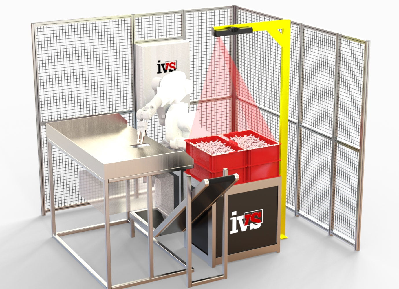
Autonomous bin picking, or the robotic selection of objects with random poses from a bin, is one of the most common robotic tasks, but it also poses some of the most difficult technological challenges. To be able to localise each part in a bin, navigate to it without colliding with its environment or other parts, pick it, and safely place it in another location in an aligned position – a robot must be equipped with exceptional vision and robotic intelligence.
Normally the 3D vision system scanner is mounted in a fixed, stationary position in the robotic cell, usually above and in-line with the bin. The scanner must not be moved in relation to the robot after the system has been calibrated. As a general rule of thumb, the more room is required for the bin picking application – including the space for robot movement, the size of the bin and parts, etc. – the larger model of the machine vision scanner required. So more resolution and pixels equates in simple terms to more precision and accuracy.
Calibration is completed with any suitable ball attached to the endpoint of the robotic arm or to the gripper. The ball needs to be made of a material that is appropriate for scanning, which means it needs to be smooth and not too reflective.
One of the problems with this approach is that the 3D vision system itself could cast a shadow on the bin and inhibit a high-quality acquisition of the scene. This problem is usually solved by making a compromise and finding the most optimal position for the scanner in relation to the bin or by manually rearranging the parts within the bin so that the vision system captures them all in the end. But is there another way?
A way to overcome this is to mount the 3D vision system on the robot itself. Of course, there are certain prerequisites to this approach (i.e. the robot can cope with the additional weight, there is room for mounting and there is cycle time available for movement), but there is some functional advantages to this approach.
For a successful calibration, the scanner must be mounted behind the very last joint (e.g. on the gripper). Any changes made to the scanner’s position after the calibration renders the calibration matrix invalid and the whole calibration procedure must be carried out again. This sort of calibration is done with a marker pattern – a flat sheet of paper (or another material) with a special pattern recognized the 3D vision system.
So what are the advantages? Well, you can’t scan your large bin with a smaller (and so lower cost) vision system scanner, because your scanner is mounted above it and its view is fixed. A small scanner mounted directly on the robotic arm allows you to get closer to the bin and choose which part of it to scan, thus potentially saving costs and helping with resolution.
Robotic mounted bin picking may also eradicate the need to darken the room where the robotic cell is located. The ambient light coming from a skylight might pose serious challenges to the deployed 3D vision system. A scanner attached to the robot can make scans of a bin from one side first and then from another, minimising the need to make any unusual adjustments to the environment.
It can also happen that the 3D vision system itself casts shadows on the bin and inhibits a high-quality acquisition of the scene. This problem is usually solved by making a compromise and finding the most optimal position for the scanner in relation to the bin or by manually rearranging the parts within the bin so that the vision system captures them all in the end. Robot mounted picking eliminates this problem as it enables the scanner to “look” at the scene from any angle and from any position.
In conclusion, there are many approaches to automated bin picking using 3D vision systems, each with their own unique approaches dependent on the environment, industrial automation needs, cost and the cycle time available for picking.
