The Ultimate Guide to Operator Guidance Systems

In today’s rapidly evolving manufacturing landscape, the role of operator guidance systems has taken centre stage. As businesses strive to enhance productivity, minimise errors, and maintain workforce engagement, innovative technologies such as augmented reality (AR) and digital work instructions are transforming the way operators interact with their tasks. This guide explores the pivotal elements of operator guidance, addressing common challenges and offering actionable insights to optimise manufacturing processes.

1. Understanding Operator Guidance

Operator guidance refers to the methods and tools designed to assist workers in executing their tasks with precision and efficiency. Whether through augmented reality, vision systems, digital instructions, or automated feedback systems, these tools aim to:

• Simplify complex tasks
• Reduce errors and rework
• Shorten training durations
• Enhance workforce versatility

The integration of such systems into manufacturing environments transforms workstations into interactive, digital ecosystems that support operators in real time. By offering real-time feedback, operators are less likely to make errors, ensuring consistency and quality throughout the manufacturing process. It also allows new operators to understand a task immediately.

Additionally, operator guidance systems improve communication on the shop floor. By aligning visual aids, auditory signals, and data analytics, they ensure that workers have access to clear and concise information. This holistic approach boosts efficiency and fosters a culture of continuous improvement.

2. The Shift Toward Digital Work Instructions

Digital work instructions have emerged as a game-changer in manufacturing, replacing traditional paper manuals with dynamic, interactive platforms. The benefits include:

Cost Efficiency: Eliminating printing and distributing manuals saves resources while promoting sustainability.
Real-Time Updates: Digital platforms ensure operators have access to the latest procedures, reducing the risk of outdated information causing errors.
Interactive Learning: Multimedia elements such as videos and interactive checkpoints enhance comprehension and retention, shorten training times, and improve task accuracy.
Streamlined Processes: Instructions tailored to specific tasks or product variants eliminate the need for manual searches, delivering the right information at the right time.

Companies adopting digital work instructions also benefit from seamless integration with Manufacturing Execution Systems (MES) and Enterprise Resource Planning (ERP) systems. This integration enables data-driven insights for continuous improvement and fosters transparency and adaptability, ensuring production goals are consistently met.

Digital work instructions are handy in high-mix, low-volume production environments where the need to adapt to new product lines quickly is critical. The ability to easily modify and distribute updated instructions enhances operational flexibility and reduces downtime.

3. Overcoming Challenges in Operator Guidance

3.1 Finding and Retaining Skilled Labour

The global shortage of skilled operators is a significant challenge for manufacturers. High turnover rates, coupled with extended training periods, can disrupt operations. Implementing operator guidance systems minimises the impact of these challenges by:

• Reducing the dependency on pre-existing expertise
• Accelerating onboarding with intuitive training modules
• Enabling lower-skilled workers to perform complex tasks effectively

By incorporating gamification elements into training modules, manufacturers can further engage employees. This approach improves learning outcomes and increases job satisfaction, reducing turnover rates. It allows work instructions to adapt to various languages automatically.

3.2 Adapting to Increased Demand

Fluctuations in customer demand often stress production capacities. Flexible guidance systems help manufacturers scale operations by:

• Training temporary workers swiftly
• Standardising processes to ensure consistent quality
• Allowing real-time adjustments based on workload variations

Advanced analytics integrated into guidance systems allow managers to predict and prepare for demand surges, optimising resource allocation.

3.3 Addressing Operator Resistance

Operator scepticism can hinder the adoption of new technologies. Concerns about micromanagement and loss of autonomy are common. To counter this, systems are designed with operator-centric features such as:

• Experience Level Functionality: Customisable instruction intensity based on operator proficiency
• Freedom in Task Execution: Allowing operators to perform tasks in their preferred sequence where feasible
• Error Prevention as Support: Real-time feedback focuses on preventing mistakes rather than penalising them

Involving operators in designing and implementing guidance systems can also mitigate resistance. By incorporating user feedback, organisations can ensure that the systems are perceived as tools for empowerment rather than oversight.

4. The Role of Augmented Reality in Operator Guidance

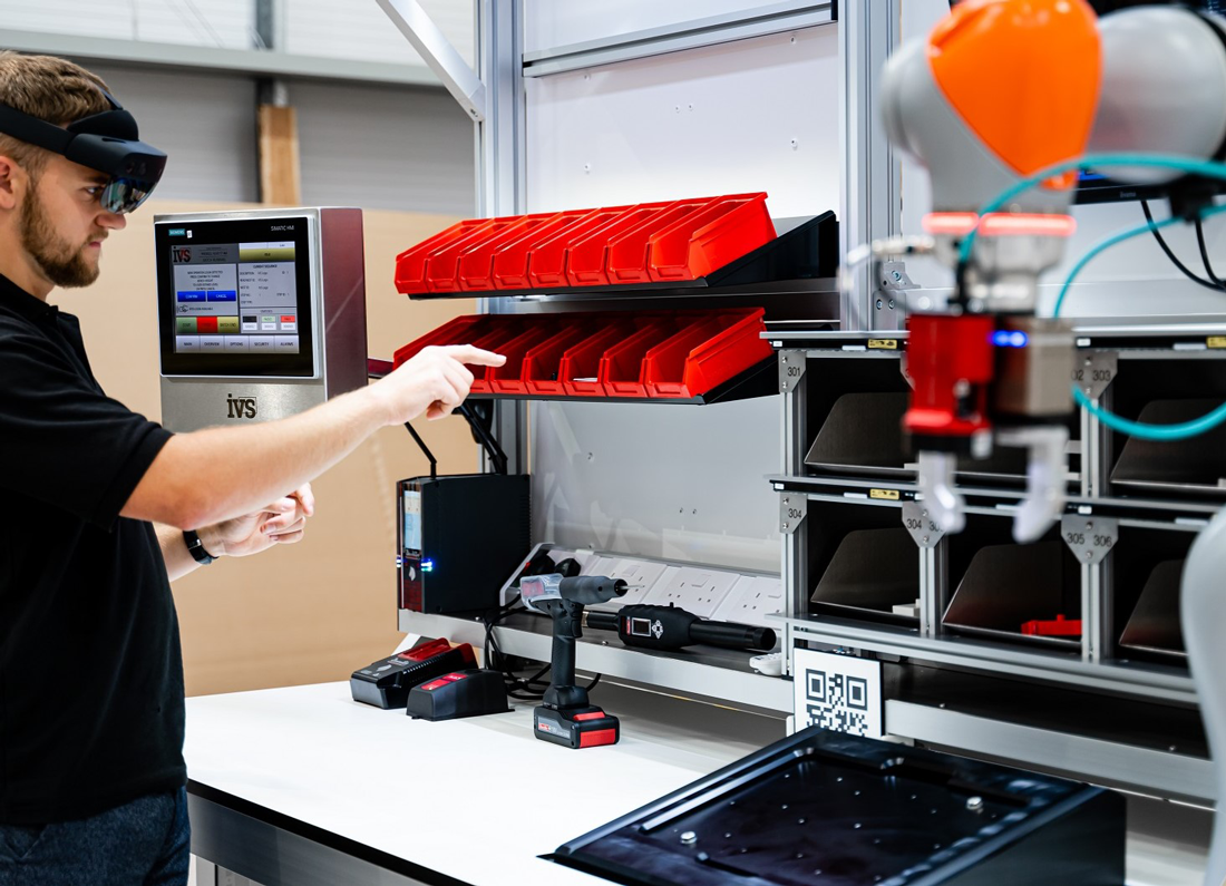
Augmented reality (AR) enhances operator guidance by overlaying digital information directly onto physical workspaces. This immersive approach offers:

Real-Time Visual Feedback: Operators receive step-by-step instructions projected onto their workbench, ensuring clarity and precision.
Reduced Cognitive Load: By focusing on one task at a time, operators can work more efficiently without memorising sequences.
Error Prevention: AR systems, integrated with sensors and smart tools, provide immediate warnings if a task is performed incorrectly.

Types of AR Implementation:

Wearables: AR glasses and headsets provide hands-free access to instructions but may cause discomfort during extended use.
Handheld Devices: Tablets offer portability but interrupt workflow when operators need both hands.
Projected AR: Systems that project instructions directly onto workspaces offer ergonomic, non-intrusive solutions ideal for industrial settings. This approach is particularly valued for its standalone nature, eliminating reliance on battery power and enhancing safety.

Projected AR also offers significant scalability, making it suitable for both small-scale operations and large industrial setups. Its ability to integrate seamlessly with existing tools and workflows ensures minimal disruption during implementation.

5. Benefits of Implementing Operator Guidance Systems

5.1 Enhanced Training
Guidance systems significantly reduce training durations by up to 50%, enabling temporary and new workers to become productive faster. Interactive features foster skill acquisition and confidence. Visual and interactive tools accelerate learning and reduce dependency on senior operators.

By incorporating real-time feedback mechanisms, these systems create a continuous learning environment. Operators can identify and correct errors on the spot, enhancing their overall proficiency over time.

5.2 Improved Quality and Efficiency
Standardised processes ensure that every operator performs tasks uniformly, minimising errors and waste. Systems that validate task completion further enhance quality assurance. By minimising rework and reducing scrap, these systems help manufacturers maintain competitive advantages.

Data from guidance systems can also be used to implement continuous improvement initiatives. By analysing patterns in errors and inefficiencies, managers can identify opportunities for process optimisation.

5.3 Adaptability and Flexibility
With customisable instructions, operators can seamlessly switch between tasks or product variants. This flexibility supports high-mix, low-volume production environments. The ability to integrate temporary or seasonal workers smoothly ensures operational continuity.

Moreover, guidance systems support cross-training initiatives, enabling workers to develop skills across multiple roles. This versatility enhances workforce agility and resilience.

5.4 Data-Driven Insights
Embedded analytics identify bottlenecks and error-prone steps, providing actionable data to optimise workflows and improve productivity. Reports generated from these systems allow supervisors to target specific areas for improvement, enhancing overall operational efficiency.

The integration of IoT devices further enhances data collection, offering deeper insights into machine performance and operator interactions. This holistic view enables more informed decision-making.

6. Empowering Operators: A Broader Perspective

Instead of focusing on a single case, the real power of operator guidance systems lies in their adaptability across diverse industries. Whether it is automotive manufacturing, electronics assembly, or medical device assembly, these systems are engineered to overcome common challenges such as complex task sequences and quality control. By integrating features like real-time feedback, customisable training modules, and seamless MES/ERP connectivity, businesses of all sizes can achieve:

• Up to 50% faster onboarding of new staff
• Streamlined multi-variant production processes
• A significant reduction in waste and rework
• Enhanced adaptability for workforce changes

This versatility highlights the universal benefits of operator guidance systems, making them indispensable tools for any forward-thinking manufacturing operation.

The ability to customise systems based on industry-specific requirements ensures that organisations can address their unique challenges effectively. From ensuring compliance in regulated industries to optimising throughput in high-volume sectors, these systems deliver measurable value.

7. The Future of Operator Guidance

As Industry 4.0 continues to evolve, operator guidance systems will play an even more critical role in bridging human expertise with advanced automation. Emerging trends include:

AI-Driven Insights: Predictive analytics to pre-empt errors and optimise training
IoT Integration: Seamless communication between tools, sensors, and guidance platforms
Personalised Experiences: Tailoring guidance to individual operator preferences and skill levels
Eco-Conscious Manufacturing: Incorporating sustainable practices through optimised resource management

By aligning with these trends, operator guidance systems will continue to serve as a cornerstone of modern manufacturing strategies. The focus on sustainability and worker well-being ensures that these systems contribute to broader organisational goals beyond operational efficiency.

Conclusion

Operator guidance with vision systems represents a pivotal advancement in manufacturing, addressing challenges from labour shortages to quality assurance. By leveraging technologies like augmented reality and digital work instructions, manufacturers can empower their workforce, reduce costs, and achieve unparalleled operational excellence. Embracing these systems is not just a step forward—it is an essential leap into the future of manufacturing. These systems’ adaptability, efficiency, and support for human-centric operations make them indispensable for achieving long-term success in a competitive global manufacturing market.

More details on IVS Operator Guidance Systems can be found here: www.industrialvision.co.uk/products/operator-guidance-platform

How automated vision technology ensures perfect pills and tablets

When you pick up a pill or tablet, it may appear small and modest, but have you ever realised how much precision goes into making it perfect? In the pharmaceutical industry, the quality of pills and tablets is determined by more than just their chemical content. These tiny goods must also meet demanding size, shape, weight, and appearance requirements. A single flaw or defect can jeopardise not just the product’s integrity but also consumer trust, hence quality control is a major responsibility.

Automated vision technology is critical in pharmaceutical manufacturing because it ensures precision and compliance throughout the entire process. These systems are critical in modern manufacturing, delivering innovative solutions that ensure each pill fulfils stringent industry standards and regulatory criteria. From detecting cosmetic faults to following tight MHRA, FDA, and GxP criteria, these advanced vision systems add precision, speed, and dependability to an otherwise daunting process.

Why Does Perfection Matter in Pharmaceutical Manufacturing?
In the pharmaceutical sector, flaws are more than just an aesthetic issue. A tablet with obvious flaws, such as black spots, cracks, or discolouration, may raise concerns about its quality and safety. Furthermore, any change from the specified dimensions, weight, or appearance may have an impact on the medication’s efficacy or raise regulatory concerns.

Pharmaceutical firms are expected to follow strict rules such as MHRA, GAMP, and GxP laws. Automated vision systems meet these standards by performing speedy and comprehensive inspections, decreasing human error, and ensuring quality control consistency. Manual inspection is just not possible for production lines that run at high speeds, hence automation is an integral aspect of the process.

Tablet and Pill Inspection: A Complicated Process
Pills, pills, and capsules come in all shapes and sizes. Tablets typically measure 5-12mm in diameter and 2-8mm thick, with curved tablets reaching lengths of up to 21mm. Capsules, on the other hand, are classified according to their size, which typically ranges from size 0 (biggest) to size 5. Regardless of these variances, producers must detect cosmetic flaws down to the nano level—a feat well beyond the human eye’s capabilities.

Some frequent defect categories that vision systems must recognise are:

  • Surface problems include dirt, foreign particles, scratches, cracks (lengthwise and diagonal), splits, and holes.
  • Anomalies in shape include dents, bends, double capping, and collapsed tablets.
  • Color discrepancies, including discolouration and uneven finishes.

How Does Automated Vision Technology Work?
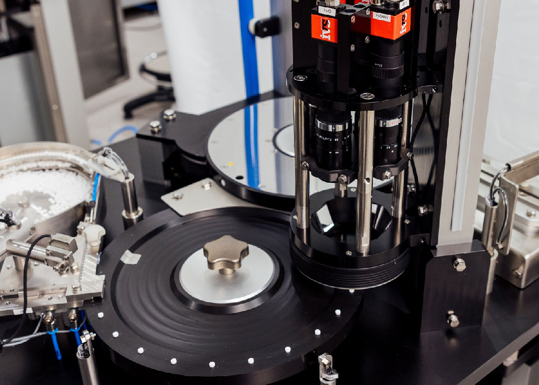
The inspection procedure starts with a high-speed feeding mechanism. Pills are carefully transferred from hoppers or bowls into the inspection channel and positioned for best viewing by the vision system. To guarantee both sides of the pill are inspected, modern systems frequently use a two-step process:
-First Side Inspection: A vacuum dial plate holds the pill in place while cameras take photos of the top surface.
-Second Side Inspection: The pill is moved to another plate and hung securely through a vacuum while cameras analyse the bottom.
This system ensures that each tablet is properly scrutinised with no blind spots.

The Magic of Multi-Camera Vision Systems.
The true value of automated vision technology comes from its capacity to deliver a 360-degree image of each tablet or pill. Multi-camera modules, which are frequently coupled with custom optics and mirrors, enable for thorough inspection. Manufacturers may take images of all sides and angles of the pill by strategically positioning cameras and mirrors, resulting in eight distinct perspectives of a single product.

These photos are evaluated by advanced algorithms that detect even the smallest imperfections, guaranteeing that only faultless products make it into packaging. The system’s capacity to eliminate blind spots is vital for performing the high-speed, high-accuracy inspections demanded by current pharmaceutical manufacturing.

Beyond Detection: The advantages of vision systems
Automated vision systems offer distinct benefits that correspond to the pharmaceutical industry’s rigorous requirements:

  • Vision systems can inspect hundreds of pills per minute without sacrificing accuracy, resulting in optimal manufacturing line efficiency.
  • Advanced imaging can detect faults as small as a few microns, invisible to the human sight.
  • Real-time data analytics in vision systems help manufacturers spot trends, foresee concerns, and take preventive action to preserve product quality.
  • Effective Compliance: Built-in checks linked with FDA, GAMP, MHRA and GxP standards ease regulatory conformity, decreasing the risk of infractions and assuring consistent product quality.
  • Vision systems reduce waste by recognising damaged pills early in the production process, saving money and resources.
  • These specific qualities make automated vision systems indispensable in modern pharmaceutical manufacturing, where precision and compliance are critical.

Innovation on the Horizon
As technology advances, so does the possibility for automated vision systems. Emerging technologies such as artificial intelligence (AI) and machine learning are improving defect detection capabilities by allowing systems to learn from prior inspections and improve with time. Additionally, integration with Internet of Things (IoT) devices enables real-time monitoring and data analysis, giving businesses with actionable insights to further improve manufacturing operations.

Final Thoughts
Automated vision technology is transforming the pharmaceutical industry by assuring that every pill and tablet meets the highest levels of quality and safety. These technologies improve manufacturing efficiency while maintaining consumer trust by combining speed, precision, and innovation.

The next time you take a pill, remember the sophisticated processes and cutting-edge technology that secured its perfection. Automated vision inspection enables manufacturers to confidently provide clean, high-quality products, one pill at a time.

How to deploy an effective vision system for automated inspection

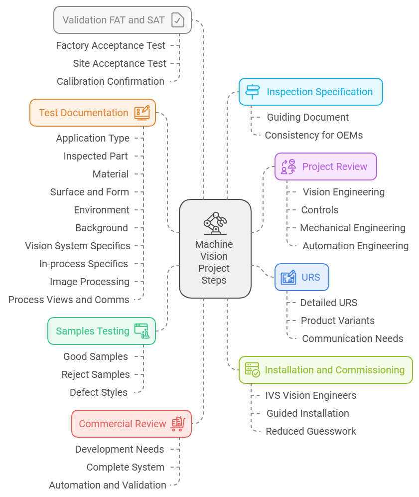
When we start developing a new vision system project or are asked to quote for a specific project, we return to the first principles of good practice for vision systems design. We have created these first principles from our millions of hours of experience developing machine vision solutions for Original Equipment Manufacturers (OEM) and end-user customers. It’s a holistic approach to a project review, from the initial understanding of the vision system elements to assessment for automation, an understanding of the process and production environment, and finally, control and factory information connectivity.

The key to this is being driven by the specification and development of a machine vision solution that will work and be robust in the long term. This might sound obvious, as why wouldn’t you design something which will work for the customer, provide long-term stability and make support (and everyone’s life) easier? But we sometimes hear of customers who have supposedly found a solution for a lower price or specification, which, when looked at in detail, proves to be a solution which won’t work, provides the customer with a lot of hassle and ends up being a quality control white elephant in their production. Vision systems have to be adequately thought out and understood. First and foremost, it must work and be robust so that the industrial automation in the line continues to run 24/7, without interruption.

So, how do we approach a machine vision project to ensure its effectiveness, I hear you say? Well, as we said, we look at the sequence of steps that will make for an effective vision system solution. This is best practice for vision system deployment and successful delivery. Where do you start:

1. User Requirement Specification (URS)/Specification/Detailed Information. The first thing to have is a very defined URS or specification to work with. Again, this might sound strange, but some customers have no specific written specifications, only an idea of a system. This is fine in the early stages, but to quote and ultimately deploy effectively, a specification is needed detailing the product, the variants, speeds, communication, quality checks required, tolerances, production information, process control and all elements of the production interaction (and rejection) that are required. For a formal medical device/pharma production URS, this will be spelt out in more detail on an individually numbered sentence-by-sentence or paragraph-by-paragraph basis, based on GAMP (Good Automated Manufacturing Practice). However, for others, it could be a few pages of written detail defining the requirements for the vision system. Whichever approach, the project needs to be defined from the get-go.

2. Samples Testing. Testing of samples is always a good idea. These are real-world samples from the production line showing the product variation on a shift-by-shift, week-by-week basis. Samples that show both good and actual reject samples are needed. Samples of varying defect styles are required to understand how such a rejection will manifest itself on the product. Depending on the project’s difference from those already known algorithms, a formal Proof of Principle may be suggested to determine how the vision system can effectively identify the rejects.

3. Test Documentation. Our proven and reliable test format drives our engineering to document the sample testing results. This allows us to record all the information on the project and provide tangible data to review in the future if the project goes ahead, so it’s a key document in the fight for effectiveness in the vision system deployment. The sheet is divided into specific areas and completed with the sample testing. It includes all details on the job, including:
-Application type: for example presence verification, gauging, code reading or Optical Character Recognition (OCR)
-Inspected Part: is the sample indicative of the real “in-production” type, how many variants are there?
-Material: is the part metallic, opaque, transparent, etc?
-Surface and Form: is it reflective, painted rough etc?
-Environment: what environment will the vision system operate in. For example, if surface detection of contamination is required, a clean room will help to reduce the false failures or debris on the surface.
-Background: how is the product presented on a fixture, and what does that look like?
-Vision System specifics: what camera head type is needed, resolution, pixel size, frame rate, spatial resolution, field of view, object distance and optics.
-In-process specifics: How fast is the product moving, what cycle time is needed, and what wavelength of light is used?
-Image processing: once all the above elements are confirmed the actual machine vision image processing needs to be reviewed. Can traditional algorithms be used or is it an AI application? How repeatable is the processing based on the product deviation over many samples? Sample images should be saved showing the test conditions and every sample reviewed.
-Process views and comms: What will we display on the production line HMI, what stats and yields need to be seen, and finally how will the system communicate with the Programmable Logic Controller (PLC) or factory information system.

4. Project Review. A multi-disciplinary team, including vision engineering, controls, mechanical engineering, and automation engineering carry out a review of the results. The team reviews testing results and assesses how this applies to the production environment, automation and interaction with other production processes. The test documentation will provide some specific angles, lighting and filters required for the vision set-up. Can the product be presented consistently to allow the defined fields of view to be seen? The whole team must agree that the project is viable and the vision testing was successful for us to progress – again, another gate to make sure the vision system deployment is effective.

5. Commercial Review. The commercial team will become involved in the project review to understand all elements of the vision system, the specific development needed, and how this translates into a complete system or machine, including all aspects of automation and validation. The commercials are agreed upon for the project.

6. Inspection Specification. Once a project is live, all of the work done in advance is transferred to the engineering team. This will lead to the development and publication of an Inspection Specification that will run through the whole project. This specification defines all elements of the vision system and the approach for inspection. It is agreed with the customer and becomes the guiding document through the project’s completion. For OEM customers who will be purchasing multiple systems, it also provides the ability to provide a consistent machine vision system from project to project.

7. Installation and Commissioning. As the project progresses, competent and experienced IVS vision engineers perform installation and commissioning. They are guided by all the information already collated and assessed, therefore reducing any guesswork about the vision system’s operation as it’s installed. This measured approach means there are no surprises or unknowns once this stage is reached, derisking the project from both sides.

8. Validation FAT and SAT. Prior to final confirmation of operation, a Factory Acceptance Test (FAT) and Site Acceptance Test (SAT) are conducted based on the vision engineering and inspection specification requirements. This rigid document tests all fail conditions of the machine vision system, robust operation over a long period, and confirmation of the calibration of the complete system.

How to deploy an effective vision system for automated inspection

Overall, these steps create a practical framework for the orderly specification and deployment of a robust and fit-for-purpose vision system. Even for our OEM customers who require multiple machines or vision systems over a long contractual period, it pays to follow the standard procedure for effective vision system deployment. The process is designed to minimise risk and provide a robust and long-service vision system that can easily be supported and maintained.

Crush Defects: The Power of Semi-Automatic Inspection

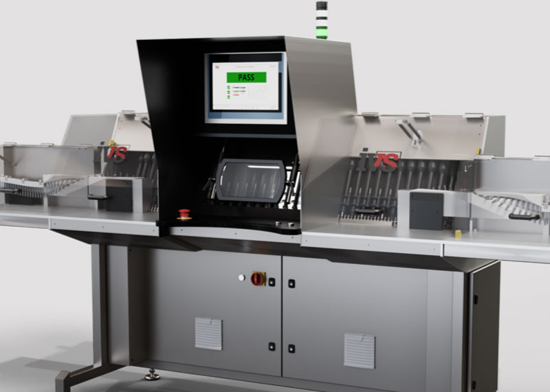
This month, we’re discussing the elements of semi-automatic inspection. This is the halfway house that pharmaceutical manufacturers have to move to from manual quality inspection (of individual products) at a bench when volumes start to increase but don’t warrant a fully automated inspection solution. The catalyst for change is when the inspection room is full of quality inspectors, and it’s time to increase the throughput of quality assessment. The semi-automatic inspection solution allows vials (liquid and lyo), syringes, cartridges and ampoules to be presented to the operator at speed to review before a magnifier, enabling manual rejection to be completed. This allows a single operator to do the job of a room of quality inspectors. This process mimics the standard GAMP manual inspection of the black and white background booths found in manual inspection, allowing for the throughput of high volumes. However, how does the semi-automatic inspection fit into the validation process and allow validation at the relevant levels?

Crush Defects: The Power of Semi-Automatic Inspection

Validation of such semi-automatic inspection must adhere to the United States Pharmacopeia (USP). The following chapters from the USP are regarded as the main literature and source for regulatory information surrounding the visual inspection of injectables:

Chapter 〈790〉 VISIBLE PARTICULATES IN INJECTIONS
Chapter 〈1790〉 VISUAL INSPECTION OF INJECTIONS
Chapter 〈788〉 PARTICULATE MATTER IN INJECTIONS

Crush Defects: The Power of Semi-Automatic Inspection

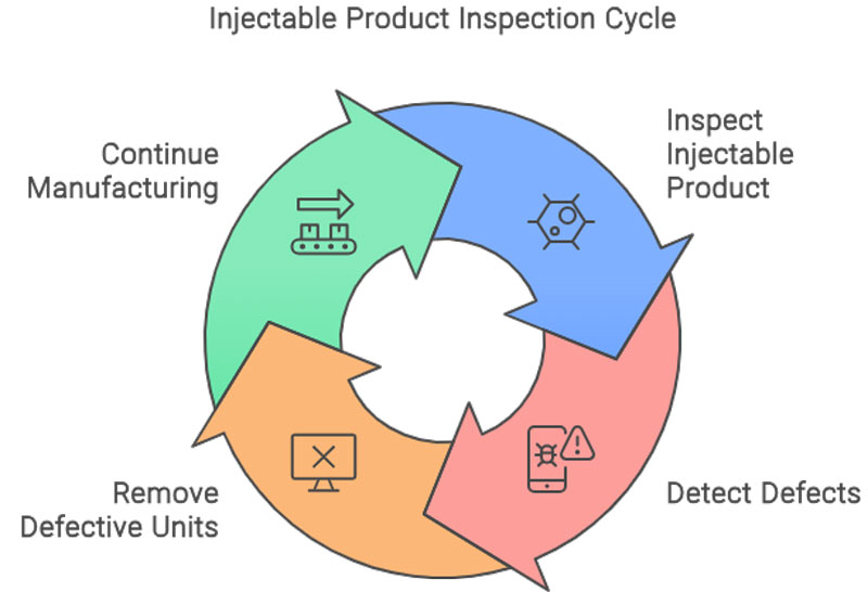
Chapter 〈790〉 establishes the expectation that each unit of injectable product will be inspected as part of the routine manufacturing process. This inspection should take place at a point when defects are most easily detected; for example, prior to labelling or insertion into a device or combination product. Semi¬automated inspection should only be performed by trained, qualified inspectors. The intent of this inspection is to detect and remove any observed defect. When in doubt, units should be removed

Crush Defects: The Power of Semi-Automatic Inspection

Defect Types

IVS semi-automatic inspection machines with operators allow for the inspection of cosmetic defects in the container and particulate matter within the fluid. The machines will enable the inspection of the following defects:

Cosmetic Defects:
• Glass cracks
• Scratches
• Missing stoppers/caps
• Improper cap/stopper closure
• Glass inclusions

Crush Defects: The Power of Semi-Automatic Inspection

Particulate Matter:
• Fibers
• Glass
• Metal
• Product Related
• Rubber

Crush Defects: The Power of Semi-Automatic Inspection

What are the particle definitions which apply to Semi-Automatic Inspection?

Extrinsic – Highest risk
Particles may originate from many sources. Those that are foreign to the manufacturing process are considered exogenous or “extrinsic” in origin; these include hair, non-process-related fibres, starch, minerals, insect parts, and similar inorganic and organic materials. Extrinsic material is generally a one-time occurrence and should result in the rejection of the affected container in which it is seen; however, elevated levels in the lot may implicate a broader contribution from the same source. These particles may carry an increased risk of microbiological or extractable contamination because less is known about their path before deposition in the product container or their interaction with the product.

Intrinsic – Medium Risk
Other particles are considered “intrinsic”, from within the process. Intrinsic particles may come from processing equipment or primary packaging materials that were either added during processing or not removed during container preparation. These primary product-contact materials may include stainless steel, seals, gaskets, packaging glass and elastomers, fluid transport tubing, and silicone lubricant. Such particles still pose the risk of a foreign body, but generally come from sterile or sanitized materials and more is known about their interactions when in contact with the product.

Inherent- Lower Risk
“Inherent” particles are considered the lowest risk as they are known to be or intended to be associated with specific product formulations. The physical form or nature of inherent particles varies from product to product and includes solutions, suspensions, emulsions, and other drug delivery systems that are designed as particle assemblies (agglomerates, aggregates). Product formulation-related particulate formation should be studied in the development phase and in samples placed on stability to determine the normal characteristics and time-based changes that can occur.

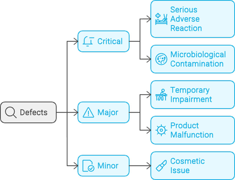
Defects are commonly grouped into classifications based on patient and compliance risk. The most common system uses three groups: critical, major, and minor. Critical defects are those that may cause serious adverse reaction or death of the patient if the product is used. This classification includes any nonconformity that compromises the integrity of the container and thereby risks microbiological contamination of the sterile product. Major defects carry the risk of a temporary impairment or medically reversible reaction, or involve a remote probability of a serious adverse reaction. This classification is also assigned to any defect which causes impairment to the use of the product. These may result in a malfunction that makes the product unusable. Minor defects do not impact product performance or compliance; they are often cosmetic in nature, affecting only product appearance or pharmaceutical elegance.

Crush Defects: The Power of Semi-Automatic Inspection

Inspection criteria

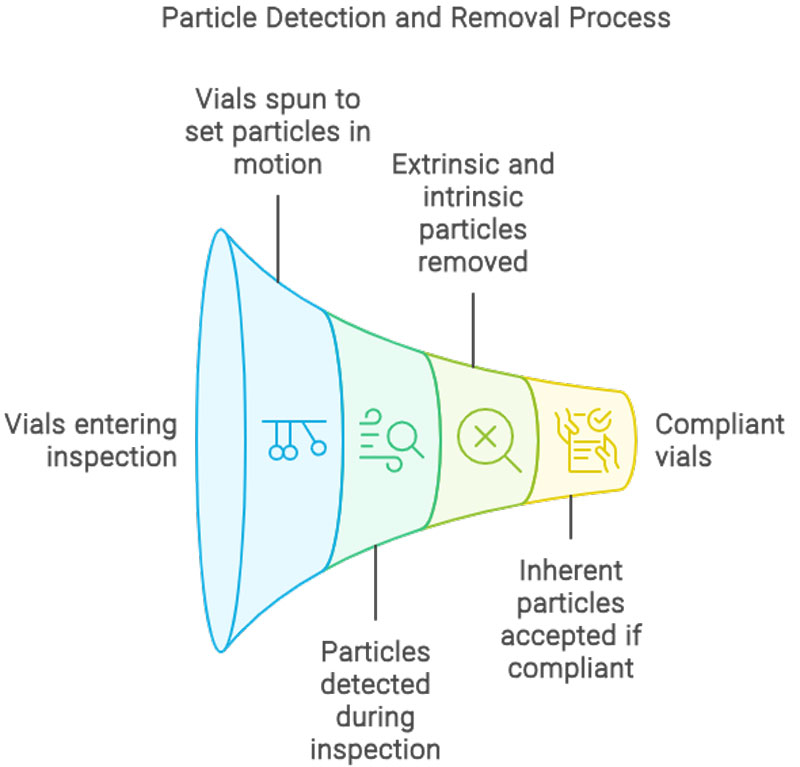
On semi-automatic inspection machines, the vials are spun up at speed prior to reaching the inspection area. This sets any visible particles in motion which aids in detection as stationary particles will be difficult to detect. Upon 100% inspection, visible extrinsic and intrinsic particles should be reliably removed. The test method allows inherent particles to be accepted if the product appearance specification allows inherent particle types. The size of particles reliably detected (2′::70% probability of detection) is generally 150 µm or larger. This Probability of Detection (POD) is dependent on the container characteristics (e.g., size, shape, transparency), inspection conditions (lighting and duration), formulation characteristics (colour and clarity), and particle characteristics (size, shape, colour, and density). For syringes the products are agitated and turned over so that no particulate matter is left in the bung and can be seen.

Crush Defects: The Power of Semi-Automatic Inspection

Critical Inspection Conditions

Light intensity
The results of the inspection process are influenced by the intensity of the light in the inspection zone. In general, increasing the intensity of the light that illuminates the container being inspected will improve inspection performance; 〈790〉 recommends light levels of 2,000-3,750 lux at the point of inspection for routine inspection of clear glass containers. Special attention should be given to assure that inspection is not performed below the lower limit of 2,000 lux.

Background and Contrast
Contrast between the defect of interest and the surrounding background is required for detection, and increased contrast improves detection. The use of both black and white backgrounds is described in 〈790〉, as well as other global pharmacopoeias. The use of both backgrounds provides good contrast for a wide range of particulate and container defects, which can be light or dark in appearance.

Inspection Rate
This is controlled by the roller travel speed. Sufficient time must be provided to allow for thorough inspection of each container; chapter 〈790〉 specifies a reference time of 10 s/container (5s each against both black and white backgrounds).

Magnification
Some inspection processes use a large magnifier to increase image size and thus increase the probability of detecting and rejecting containers with defects near the threshold of detection. Most lenses used during this inspection process are around X2 magnification.

Crush Defects: The Power of Semi-Automatic Inspection

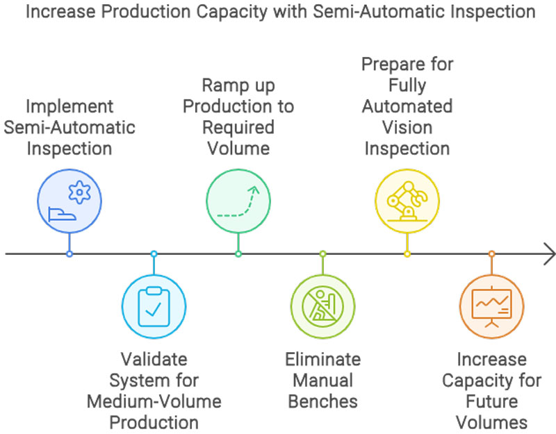
Overall, Semi-Automatic Inspection is a necessary step when pharmaceutical manufacturers move into medium-volume production. Validating such systems allows production to ramp up to the required volume without the need for manual benches and provides capacity for future volumes before fully automated vision inspection with vision systems. More details on how to use Semi-Automatic inspection for regulatory compliance can be found here.

Why industrial vision systems are replacing operators in factory automation (and what they aren’t doing!)

This month, we’re following on from last month’s post.
We’ve all seen films showing the dystopian factory landscape a few hundred years in the future. Flying cars against a grey backdrop of industrial scenery. Robots serving customers at a fictitious future bar, and probably – if they showed a production line, it would be full of automatons and robots. We will drill down on the role that industrial vision systems can have on the real factory production line. Is it the case that in the future, all production processes will be replaced with automated assembly, coupled with real-time quality inspection? Intelligent robots which can handle every production process?

Let’s start with what’s happening now, today. It’s certainly the case that machine vision has developed rapidly over the last thirty years. We’ve gone from slow scientific image processing on a 386 computer (look it up!) to AI deep learning running at hundreds of frames per second to allow the real-time computation and assessment of an image in computer vision. But this doesn’t mean that every process has (or can be) replaced with industrial vision systems, but what’s stopping it from being so?

Well, the main barrier to this is the replication of the human dexterity and ability to manoeuvre the product in delicate (compared to an industrial automated process) ways. In tandem with this is the ability for a human to immediately switch to a different product mix, size and type of product. So you could have a human operator construct a simple bearing in a matter of seconds, inspect it – and then ask them to build next a completely different product, such as a small medical device. With some training and show how, this information exchange can be done and the human operator adapts immediately. But a robot would struggle. Not to say it couldn’t be done, but with today’s technology, it takes effort. This is the goal of Industry 5.0, the next step generation from Industry 4.0 flexible manufacturing. Industry 5.0 is a human-centric approach, so industry understanding that humans working in tandem with robotics, vision, and automation is the best approach.

So we need to look at industrial vision in the context of not just whether the image processing can be completed (be it with traditional algorithms or AI deep learning), but also how we can present the product meaningfully at the correct angles to assess it. Usually, these vision inspection checks are part and parcel with an assembly operation, which requires specific handling and movement (which a human is good at). This is the reason most adoption of machine vision happens on high throughput, low variation manufacturing lines – such as large-scale medical device production where the same product is validated and will be manufactured in the same way over many years. This makes sense – the payback is there and automation can be applied for assembly and inspection in one.

But what are the drivers for replacing people on production lines with automated vision inspection?
If the task can be done with automation and vision inspection, it makes sense to do it. Vision inspection is highly accurate, works at speed and is easy to maintain. Then there are the comparisons comparing the processes to a human operator. Vision systems don’t take breaks, don’t get tired, and robots don’t go to parties (I’ve never seen a robot at a party) – so they don’t start work in the morning with their minds not on the task at hand! So, it makes sense to move towards automated machine vision inspection wherever possible in a production process, and this represents huge growth in the adoption of industrial vision systems in the coming years.

If the job is highly complex in terms of intricate build, with many parts and variants, then robots, automation and vision systems are not so easy to deploy. However, with the promise of Industry 5.0, we have the template of the future – moving towards an appreciation of including the human operator in factory automation – combining humans with robots, automation, augmented reality, AI and automated inspection. So, the dystopian future might not be as bad as the filmmakers make out, with human operators still being an integral part of the production process.

Catalysts of change: How robots, machine vision and AI are changing the automotive manufacturing landscape

This month, we are discussing the technological and cultural shift in the automotive manufacturing environment caused by the advent of robotics and machine vision, coupled with the development of AI vision systems. We also drill down on the drivers of change and how augmented reality will shape the future of manufacturing technology for automotive production.

Robots in Manufacturing
Robots in manufacturing have been used for over sixty years, with the first commercial robots used in mass production in the 1960s – these were leviathans with large, unwieldy pneumatic arms, but they paved the way for what was to come in the 1970s. At this time, it was estimated that the USA had 200 such robots [1] used in manufacturing; by 1980, this was 4,000 – and now there are estimated to be more than 3 million robots in operation [2]. During this time the machine vision industry has grown to provide the “eyes” for the robot. Machine vision uses camera sensor technology to capture images from the environment for analysis to confirm either location (when it comes to robot feedback), quality assessment (from presence verification through to gauging checks) or simply for photo capture for warranty protection.

The automotive industry is a large user of mass-production robots and vision systems. This is primarily due to the overall size of the end unit (i.e. a built car), along with vision systems for confirmation of quality due to the acceptable parts per million failure rate (which is extremely low!). Robots allow repetitive and precise assembly tasks to be completed accurately every time, reducing the need for manual labour and providing a faster speed for manufacturing.

Automating with industrial robots is one of the most effective ways to reduce automotive manufacturing expenses. Factory robots help reduce labour, material, and utility expenses. Robotic automation reduces human involvement in manufacturing, lowering wages, benefits, and worker injury claims.

AI Machine Vision Systems
Deep learning in the context of industrial machine vision teaches robots and machines to do what comes naturally to humans, i.e. to learn by example. New multi-layered “bio-inspired” deep neural networks allow the latest machine vision solutions to mimic the human brain activity in learning a task, thus allowing vision systems to recognise images, perceive trends and understand subtle changes in images that represent defects. [3]

Machine vision performs well at quantitatively measuring a highly structured scene with a consistent camera resolution, optics and lighting. Deep learning can handle defect variations that require an understanding of the tolerable deviations from the control medium, for example, where there are changes in texture, lighting, shading or distortion in the image. Deep-learning vision systems can be used in surface inspection, object recognition, component detection and part identification. AI deep learning helps in situations where traditional machine vision may struggle, such as parts with varying size, shape, contrast and brightness due to production and process constraints.

Augmented Reality in Production Environments
In industrial manufacturing, machine vision is primarily concerned with quality control, which is the automatic visual identification of a component, product, or subassembly to ensure that it is proper. This can refer to measurement, the presence of an object, reading a code, or verifying a print. Combining augmented, mixed reality with automated machine vision operations creates a platform for increased efficiency. There is a shift towards utilising AI machine vision systems (where applicable!) to improve the reliability of some quality control checks in vision systems. Then, combine that assessment with the operator.

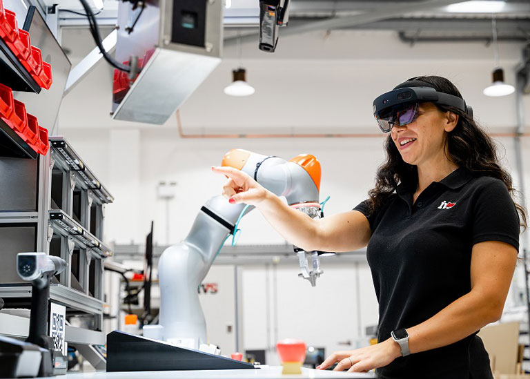
Consider an operator or assembly worker sitting in front of a workstation wearing wearable technology like the HoloLens or Apple Vision Pro (an augmented reality headset). An operator could be putting together a sophisticated unit with several pieces. They can see the tangible objects around them, including components and assemblies. They can still interact with digital content, such as a shared document that updates in real time to the cloud or assembly instructions. That is essentially the promise of mixed reality.

The mixed-reality device uses animated prompts, 3D projections, and instructions to guide the operator through the process. A machine vision camera is situated above the operator, providing a view of the scene below. As each step is completed and a part is assembled, the vision system automatically inspects the product. Pass and fail criteria can be automatically projected into the operator’s field of sight in the mixed reality environment, allowing them to continue building while knowing the part has been inspected. In the event of a rejected part, the operator receives a new sequence “beamed” into their projection, containing instructions on how to proceed with the failed assembly and where to place it. When integrated with machine vision inspection, mixed reality has become a standard aspect of the production process. Data, statistics, and important quality information from the machine vision system are shown in real time in the operator’s field of view.

Robots, AI Vision Systems and Augmented Reality
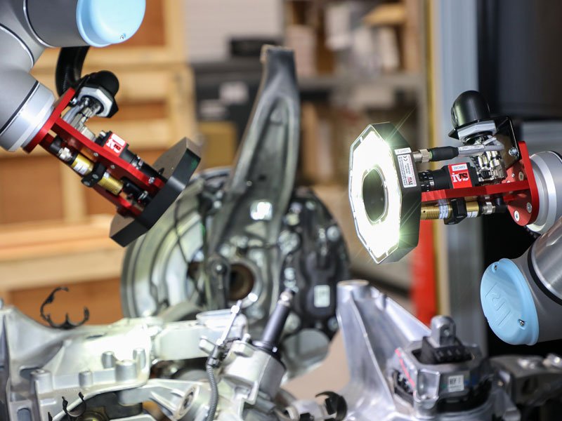
Let’s fast forward a few years and see what the future looks like. Well, it’s a combination of all these technologies as they continue to develop and mature. So AI vision systems mounted on cobots help with the manual assembly, while the operator wears an augmented reality headset to direct and guide the process for an unskilled worker. Workers are tracked while all tasks are being quality assessed and confirmed, while data is stored for traceability and warranty protection.

In direct automotive manufacturing, vision systems will become easier to use as large AI deep-learning datasets become more available for specific quality control tasks. These datasets will continue to evolve as more automotive and tier one and two suppliers use AI vision to monitor their production, allowing quicker deployment and high-accuracy quality control assessment across the factory floor.


References

Why you should transition your quality inspection from shadowgraphs to automated vision inspection

The shadowgraph used to be the preferred method, or perhaps the only method for the quality control department to check the adherence to measurement data. These typically vertical projectors have a plate bed, with parts laid on it, and the light path is vertical. This allows a silhouette and profile of the part to be shown to the operators as an exact representation of the part in black, but projected at a much higher magnification. These projectors are best for flat, flexible parts, washers, O rings, gaskets and parts that are too small to hold, such as very small shafts, screws etc. They are also used in orthopedic manufacturing to view profiles and edges of joint parts.

So, this old-fashioned method involves projecting a silhouette of the edge of the product or component. This projection is then overlaid with a clear (black-lined) drawing of the product showing some additional areas where the component shouldn’t stray into. The operator chooses the overlay from a bunch available, based on the part number of the part. This is laid over the projection and manually lined up with the tolerances shown as a thick band in key areas for quality checking. For example, if you’re an orthopedic joint manufacturer and are coating your product with an additive material, you might use a shadowgraph to check the edges of the new layer. The shadowgraph will project a magnified representation of the component to compare against.

Some optical comparators and shadowgraphs have developed to a level where they are combined with a more modern graphical user interface (GUI) and are digital to make overlays easier to check, coupled with the ability to take manual measurements.

Ultimately though, all these types of manual shadowgraphs take time to use, are manually intensive and are totally reliant on an operator to make the ultimate decision on what is a pass and a fail. You also have no record of what the projection looked like and the whole process takes time. This all leads to a loss of productivity and makes your Six Sigma quality levels dependent on an operator’s quality check, and as we all know, manual inspection (even 200% manual inspection) is not a reliable method for manufacturers to keep their quality levels in check. Operators get tired and there is a lack of consistency between different people in the quality assessment team.

But for those products with critical-to-quality measurements, the old shadowgraph methodology can now be replaced with a fully automated metrology vision system to reduce the reliance on the operator in making decisions, coupled with the ability to save SPC data and information.

In this case, the integration of ultra-high-resolution vision systems, in tandem with cutting-edge optics and collimated lighting, presents a formidable alternative to manual shadowgraphs, ushering in an era of automation. With this advancement, operators can load the product, press a button, and swiftly obtain automatic results confirming adherence to specified tolerances. Furthermore, all pertinent data can be meticulously recorded, with the option to enable serial number tracking, ensuring the preservation of individual product photos for future warranty claims. This transition not only illuminates manufacturing processes but elevates them to a brighter, six-sigma enhanced quality realm. Moreover, these systems can be rigorously validated to GAMP/ISPE standards, furnishing customers with an unwavering assurance of consistently superior quality outcomes.

For your upcoming quality initiatives or product launches, consider pivoting towards automated vision system machines, transcending the limitations of antiquated shadowgraph technology and operator-dependent assessments. Embrace the superior approach that is now within reach, and steer your manufacturing quality towards a future defined by precision, efficiency, and reliability.

By embracing automated vision systems, manufacturers streamline processes and ensure unparalleled precision and consistency in product quality. This shift represents a pivotal leap forward in manufacturing excellence, empowering businesses to meet and exceed customer quality expectations while navigating the ever-evolving landscape of modern production.

How to create data-driven manufacturing using automated vision metrology systems

Applying automated vision metrology technologies for process control before, during and after assembly and machining/moulding is now a prerequisite in any production environment, especially in the orthopaedic and additive manufacturing industries. This month, we’re drilling down on the data and knowledge you can create for your manufacturing process when deploying vision metrology systems for production quality control. Let’s face it – we all want to know where we are versus the production schedule!

What are “vision metrology” systems and machines?

It’s the use of non-contact vision systems and machines using metrology grade optics, lighting and software algorithms to allow increased throughput of quality control inspection and data collection in real-time for the production process.

What are the benefits of vision metrology systems?

Before we look at the data available on such systems and how they can be utilised to create data-driven production decisions, we should look at the benefits of automated vision metrology systems. This, combined with the data output, clearly focuses on why such systems should be deployed in today’s production environments.

Increased throughput. One of the main drivers and benefits of using automated vision metrology systems is the higher throughput compared to older contact and probing CMM approaches. Coupled with integration into autoload and autotending options, the higher production rates of deploying automated vision metrology allow for faster production and increased output from the factory door.

Better yields. As the systems are non-contact, there is no chance of damage or marking of the product, which is the risk with probing and contact inspection solutions. Checking quality through automated vision allows yields to improve across the production process.

Faster reaction to manufacturing issues. Data is king in the fast-moving production environment. Real-time defect detection, seeing spikes in quality and identifying quality issues quicker, allows production managers to react faster to changes or faults in manufacturing faults. Vision metrology allows immediate review and analysis of statistical process control on a batch, shift and ongoing basis. Monitor live progress of work orders as they happen.

Less downtime. With no contact points and fewer moving parts, maintenance downtime is minimal when applying automated vision metrology machines. Maintenance can be used for other tasks and increases productivity across the manufacturing floor.

Guarantees your quality level. Ultimately, the automated vision metrology machine is a goal-keeper. This allows the quality and production team to sleep easy, knowing that parts are not only being inspected, but also providing warranty protection via a photo save of every product through production.

How do we get data from an automated vision metrology quality control system?

This is where the use of such vision technology gets interesting. The central aspect is the quality control and automated checking of crucial measurements (usually critical to quality CTQ characteristics). Still, the data driving the quality decision is paramount for the manager. The overall data covers a range of data objects that could potentially be needed when running a modern manufacturing plant. These include OEE data, SPC information, shift records, KPI metrics, continuous improvement information, root cause analysis, and data visualisation.

OEE Data (Overall Equipment Effectiveness). The simplest way to calculate OEE is the ratio of fully productive time to planned production time. Fully productive time is just another way of saying manufacturing only good parts as quickly as possible (at the ideal cycle time) with no stop time. A complete OEE analysis includes availability (run time/planned production time), performance ((ideal cycle time x total count)/run time) and quality (good count/total count). The vision metrology data set allows this data to be easily calculated. The data is stored within the automated vision metrology device or sent directly to the factory information system.

Statistical Process Control (SPC) is used in industrial manufacturing quality control to manage, monitor, and maintain production processes. The formal term is “the use of statistical techniques to control a process or production method”. The idea is to make a process as efficient as possible while producing products within conformance specifications with as little scrap as possible. Vision metrology allows vital characteristics to be analysed at speed on 100% of product, compared to the slow, manual load CMM route. SPC data can be displayed on the vision system HMI, and immediate decisions can be made on the process performance and data presentation.

Shift records are part of the validation and access control system for the vision system used in vision metrology. This stops operators from accessing certain features and logging all information against a specific shift operator or team. Data analytics allow trends in operator handling and contribute to the data provided by the system. You may see a spike in quality concerns from a specific shift or operator; these trends can easily be tracked and traced.

KPI metrics are Key Performance Indicators normally specific to the manufacturing site. However, these invariably include monitoring the quality statistics, OEE, process parameters, environmental factors (e.g. temperature and humidity), shift data, downtime and metrology measurements. This is all part of understanding how certain situations impact the output from processes and how levels can be maintained.

Continuous Improvement is the process to improve a manufacturing facility’s product and service quality. Therefore, the data and images from any automated vision metrology machine play an important role in providing live data related to Six Sigma and real-time monitoring of the ppm (parts per million) failure rate within the facility.

Root cause analysis of manufacturing issues is challenging without tangible data from a quality inspection source. The ability to review product images at the point of inspection (with the date and time stamped information), coupled with the specific measurement data, allows easier and quicker root cause analysis when problems crop up.

Data visualisation is now built into modern automated vision metrology systems. The production manager and operators can see quality concerns, spikes in rejects, counts of good and bad, shift data, and live SPC all in a single screen. This can be displayed locally or sent immediately to the factory information system.

By utilising the latest-generation automated vision metrology systems manufacturers can now build a fully-integrated data driven production environment. They are allowing easier control based on accurate, immediate information and photos of products running through production.

Machine vision vs computer vision vs image processing

We’re often asked – what’s the difference between machine vision and computer vision, and how do they both compare with image processing? It’s a valid question as the two seemingly similar fields of machine vision and computer vision both relate to the interpretation of digital images to produce a result from the image processing of photos or images.

What is machine vision?
Machine vision has become a key technology in the area of quality control and inspection in manufacturing. This is due to increasing quality demands and the improvements it offers over and above human vision and manual operation.

Definition
It is the ability of a machine to consequentially sense an object, capture an image of that object, and then process and analyse the information for decision-making.

In essence, machine vision enables manufacturing equipment to ‘see’ and ‘think’. It is an exciting field that combines technologies and processes to automate complex or mundane visual inspection tasks and precisely guide manufacturing activity. In an industrial context, it is often referred to as ‘Industrial Vision’ or ‘Vision Systems’. As the raw image in machine vision are generally captured by a camera connected to the system in “real-time” (compared to computer vision), the disciplines of physics relating to optical technology, lighting and filtering are also part of the understanding in the machine vision world.

So, how does this compare to computer vision and image processing?
There is a great deal of overlap between the various disciplines, but there are clear distinctions between the groups.

Input Output
Image processing Image is processed using algorithms to correct, edit or process an image to create a new better image. Enhanced image is returned.
Computer vision Image/video is analysed using algorithms in often uncontrollable/unpredictable circumstances. Image understanding, prediction & learning to inform actions such as segmentation, recognition & reconstruction.
Machine vision Use of camera/video to analyse images in industrial settings under more predictable circumstances. Image understanding & learning to inform manufacturing processes.

Image processing has its roots in neurobiology and scientific analysis. This was primarily down to the limitations of processor speeds when image processing came into the fore in the 1970’s and 1980’s—for example, processing single images following the capture from a microscope-mounted camera.

When processors became quicker and algorithms for image processing became more adept at high throughput analysis, image processing moved into the industrial environment, and industrial line control was added to the mix. For the first time, this allowed an analysis of components, parts and assemblies as part of an automated assembly line to be quantified, checked and routed dependent on the quality assessment, so machine vision (the “eyes of the production line”) was born. Unsurprisingly, the first industry to adopt this technology en mass was the PCB and semiconductor manufacturers, as the enormous boom in electronics took place during the 1980s.

Computer vision crosses the two disciplines, creating a Venn diagram of overlap between the three areas, as shown below.

Machine vision vs computer vision vs image processing

As you can see, the work on artificial intelligence relating to deep learning has its roots in computer vision. Still, over the last few years, this has moved over into machine vision, as the image processing learnt from biological vision, coupled with cognitive vision moves slowly into the area of general purpose machine vision & vision systems. It’s rarely a two-way street, but some machine vision research moves back into computer vision and general image processing worlds. Given the more extensive reach of the computer vision industry, compared to the more niche machine vision industry, new algorithms and developments are driven by the broader computer vision industry.

Machine vision, computer vision and image processing are now broadly intertwined, and the developments across each sector have a knock-on effect on the growth of new algorithms in each discipline.

4 common red flags in your product design that will cause you trouble during automated vision inspection

This month, we’re going to discuss the aspects of design in your product which could affect the ability to apply automated visual inspection using vision systems to the production process. This can be a frustrating aspect for the engineering and quality managers when they’ve been asked to safeguard bad products going out of the door using machine vision, but there has been no attempt up the chain at the product design stages to either design the product in an effective way to make it simple to manufacture or to apply vision inspection to the process. Once the design has been signed off and validated, it’s often extremely difficult to get small changes instigated, and engineering is then tasked with the mass production and assembly of a product, with in-line visual inspection required.

Very often in medical device manufacturing, due to the long lifetime and cycles of products, the design was conceived months, or even years before it goes through a process of small batch production, before moving to mass production at high run rates – all this with the underlining aspect of validation to GAMP and FDA production protocols. This is the point when automated inspection will be integral to the quality and safeguarding of the consumer as part of the manufacturing process.

From our experience, we see the following red flags which could have been addressed at the design phase, which make the vision system more difficult to design and run.

1. Variants. Often, there can be too many variants of a product with additional variants of sub-assemblies, which means the number of final product variations can run to hundreds. While the vision system may be able to cope with this variation, it makes set-up more costly and ongoing maintenance more difficult. Sometimes, these variations are due to multiple customers down the line wanting subtle changes or unique part numbers, which the design team happily accommodate with no thought on the impact on the manufacturing process. The more variation which can be removed from the design phase, the easier and more cost-effective a solution for machine vision inspection will be.

2. Lack of specification in surface/material conditions. The settings for a machine vision system will depend on a product’s surface and material conditions. This is especially critical in surface inspection or any process where the segmentation of the background is required from the foreground – so presence verification, inclusion detection and even edge detection for gauging and measurement in machine vision. Suppose conditions vary too much due to a lack of specification on colour or surface being included in the design. This variation can make the vision system more susceptible to false failures or higher maintenance. While latest-generation artificial intelligence (AI) vision systems are making such analysis easier and less prone to failure in these conditions, having as little deviation in your incoming image quality for vision inspection makes sense. The design should include a specification on the surface conditions expected for repeatable manufacturing and inspection, which, for example, in plastic mould colour specification can be challenging to specify.

3. Inability to see the inspection area. In the past, we’ve been asked to automatically inspect surfaces which can’t be seen due to a lack of clear view from any angle. The product’s design is such that perhaps datum edges and points are too far away and not easily accessible. The design could be such that an overhang or other feature obscures the view. This is often the case in large sub-assemblies where the datum edge can be in a completely different area and angle to the area where vision inspection will be applied. Design engineers should assess the feasibility of applying automated inspection to the process to account for how easily the vision system can access certain areas and conditions. We often discuss such applications with manufacturing engineers, with the frustration from their side that the design engineers could have incorporated cut-outs or areas which would have provided a clear line of sight for the vision system to be applied.

4. Handling. Products should be designed to be easily handled, fed and presented to a vision system as part of the process. There will nearly always be a contact surface on tooling for handling, which will then limit the area where the vision system can view. Sometimes, this surface requires critical inspection, and the site is obscured due to the product’s design. For example, in syringe body inspection, the plastic body can be held by the top and the bottom and rotated, meaning some areas of the mould are not visible. If a lip had been designed in, the part could have been inspected twice, held differently, thus providing 100% inspection of the entire surface. Small design changes can impact both the manufacturing and automated vision inspection process. Smaller products can be inspected on glass dials and fixtures to mitigate this issue, but the design team should consider these issues at the start of the design process.

Product design needs to get input from the manufacturing and quality team early in the design process. Now vision systems are a standard part of the modern automated production process and an invaluable tool in the industry 4.0 flexible production concept; thought needs to be given to how subtle design changes and more detailed specification requirements on colour and surface quality in the design stage can help the integration and robust use of vision systems.

Connecting your vision system to the factory, everything you need to know

There has been a rapid move over the last few years from using vision systems not just for stand-alone, in-line quality control processes, but to drill down and use the information which is created, assessed and archived through the automated vision system.

When vision systems first started being used in numbers in the early 1990’s, the only real option of connection to the production line PLC (programmable logic controller) was through hardwired digital I/O (PNP/NPN), simply acting like a relay to make a decision on product quality and then to trigger a reject arm or air blast to remove the rogue product. The next evolution from there was to start to save some of the basic data at the same time as the inspection process took place. Simple statistics on how many products had passed the vision system inspection and how many had been rejected. This data could then either be displayed on the PLC HMI in simple form or via rudimentary displays on the vision system. From there, communication started with the RS-232 serial line, and this morphed into USB and onto TCP/IP.

The Fieldbus protocol was the next evolution of communication with vision systems. From the standpoint of the user, the fieldbus looked to be state-based, similar to digital I/O. In reality, the data was exchanged serially through a network. Because these messages were sent on a clock cycle, the information was delayed. The benefit of Fieldbus over digital I/O was that each data exchange package of several hundred to 1,000 bytes was exchanged. PROFIBUS, CC-Link, CANopen, and DeviceNet were among the first protocols to be created. While fieldbuses of the first generation utilised serial connections to exchange data, fieldbuses of the second generation used Ethernet. As a result, the technology was sometimes referred to as “Industrial Ethernet” as it evolved, but the term’s meaning is slightly ambiguous.

When compared to serial data transfer, Ethernet enables substantially more data to be sent. However, using Ethernet as a fieldbus medium has the problem of having non-deterministic transmission timings. To obtain enough real-time performance, several Industrial Ethernet protocols such as PROFINET, EtherNet/IP, Ethernet Powerlink, or EtherCAT typically expanded the Ethernet standard (to the Common Industrial Protocol, CIP). For PC-based vision systems, some of these expansions are implemented in hardware, which necessitates the insertion of an expansion card in the vision controller unit.

So, the big evolution came with the support of this “industrial ethernet” communication, so vision systems now use a unified standard supporting real-time Ethernet and Fieldbus systems for PC-based automation. This allows for data to be transferred and exchanged with the PLC through ethernet protocols on a single connection. The benefit is the reduction in complex and costly cabling, easy integration and fast deployment of vision systems. Ethernet is characterised by the large amount of data that can be transferred.

This allows for the seamless and simple integration with all standard PLCs, such as Allen-Bradley, Siemens, Schneider, Omron and others – directly to the vision systems controller unit. Vision system data can be displayed on the PLC HMI, along with the vision HMI, where required.

The most common protocols are:
Profinet — This industrial communications protocol is defined by Profibus International and allows vision systems to communicate with Siemens PLCs and other factory automation devices which support the protocol.

EtherNet/IP — This Rockwell-defined protocol enables a vision system to connect to Allen-Bradley PLCs and other devices.

ModBus/TCP — This industrial network protocol is defined by Schneider Electric and permits direct connectivity to PLCs and other devices over Ethernet.

This progress was and is being accompanied by an increase in the resolutions of industrial cameras. Industrial cameras for machine vision inspection are not always up to date with the commercial world of smartphones. This is largely because the quality necessary for automatic vision assessment is considerably greater than the quality required for merely seeing a photo (i.e. you don’t worry about a dead pixel when looking at your holiday pics!). As a preserved picture archive for end-of-line photo archiving in an industrial environment, high-resolution image quality is now important. In addition to connecting to the line PLC, vision systems must now link to the whole factory network environment and industrial information systems. Vision systems may now interact directly with production databases, with every image of every product leaving the factory gates being taken, recorded and time-stamped, and even linked to a batch or component number via serial number tracking. Now, vision systems are not only used as a goalkeeper to stop bad products from going out the door, but also as a warranty protection providing tangible image data for historic record keeping.

In conclusion, the industrial ethernet connection is now the easiest and fastest way to integrate vision system devices into an automated environment. The ease of connection, the lower cost of cabling, and the use of standard protocols make it a simple and effective method for high-speed communication, coupled with database connections for further image and data collection from the vision system. Vision systems are now linked to complete factory line control and command centres for fully immersive data collection.

How to calibrate optical metrology systems to ensure precise measurements

Optical metrology systems play a crucial role in various industries, enabling accurate and reliable measurements for quality control, inspection, and manufacturing processes. To ensure precise and consistent results, it is essential to calibrate these systems meticulously. By understanding the significance of calibration, considering key factors, and implementing regular calibration practices, organizations can optimise the performance of these systems. Accurate measurements obtained through properly calibrated optical metrology systems empower industries to maintain quality control, enhance efficiency, and drive continuous improvement.

How to calibrate your industrial vision system.

We’re often asked about the process for carrying out calibration on our automated vision inspection machines. After all, vision systems are based on pixels whose size is arbitrarily dependent on the sensor resolutions, fields-of-view and optical quality. It’s important that any measurements are validated and confirmed from shift-to-shift, day-to-day. Many vision inspection machines are replacing stand-alone slow probing metrology-based systems, or if it’s an in-line system, it will be performing multiple measurements on a device at high speed. Automating metrology measurement helps reduce cycle time and boost productivity in medical device manufacturing; therefore, accuracy and repeatability are critical.

In the realm of optical metrology, the utilisation of machine vision technology has brought about a transformative shift. However, to ensure that the results of the vision equipment have a meaning that everyone understands, the automated checks must be calibrated against recognised standards, facilitating compliance with industry regulations, certifications, and customer requirements.

The foundational science that instils confidence in the interpretation and accuracy of measurements is known as metrology. It encompasses all aspects of measurement, from meticulous planning and execution to meticulous record-keeping and evaluation, along with the computation of measurement uncertainties. The objectives of metrology extend beyond the mere execution of measurements; they encompass the establishment and maintenance of measurement standards, the development of innovative and efficient techniques, and the promotion of widespread recognition and acceptance of measurements.

For metrology measurements, we need a correlation between the pixels and the real-world environment. For those of you who want the technical detail, we’re going to dive down into the basis for the creation of individual pixels and how the base pixel data is created. In reality, the users of our vision systems need not know this level of technical detail, as the main aspect is the calibration process itself – so you can skip the next few paragraphs if you want to!

The camera sensor is split into individual pixels in machine vision. Each pixel represents a tiny light-sensitive region that, when exposed to light, creates an electric charge. When an image is acquired, the vision system captures the amount of charge produced at each pixel position and stores it in a memory array. A protocol is used to produce a uniform reference system for pixel positions. The top left corner of the picture is regarded the origin, and a coordinate system with the X-axis running horizontally across the rows of the sensor and the Y-axis running vertically down the columns is utilised.

The pixel positions inside the image may be described using the X and Y coordinates in this coordinate system. For example, the top left pixel is called (0,0), the pixel to its right is called (1,0), the pixel below it is called (0,1), and so on. This convention enables the image’s pixels to be referred to in a consistent and standardised manner. So this method provides a way (in combination with sub-pixel processing) to provide a standard reference coordinate position for a set of pixels combined to create an edge, feature or “blob”.

In machine vision, metrology calibration involves the mapping of the pixel coordinates of the vision system sensor back to real-world coordinates. This “mapping” ties the distances measured back to the real-world measurements, i.e., back to millimetres, microns or other defined measurement system. In the absence of a calibration, any edges, lines or points measured would all be relative to pixel measurements only. But quality engineers need real, tangible measurements to validate the production process – so all systems must be pre-calibrated to known measurements.

The process of calibration ensures traceability of measurements to recognised standards, facilitating compliance with industry regulations, certifications, and customer requirements. It enhances the credibility and trustworthiness of measurement data.

How do you calibrate the vision system in real-world applications?

Utilising certified calibration artifacts or reference objects with known dimensions and properties is essential. These standards serve as benchmarks for system calibration, enabling the establishment of accurate measurement references. Proper calibration guarantees that measurements are free from systematic errors, ensuring the reliability and consistency of the data collected. The method of calibration will depend on if the system is a 2D or 3D vision system.

For a 2D vision system, common practice is to use slides with scales carved or printed on them, referred to as micrometre slides, stage graticules, and calibration slides. There is a diverse range of sizes, subdivision accuracy, and patterns of the scales. These slides are used to measure the calibration of vision systems. These calibration pieces are traceable back to national standards, which is key to calibrating the vision inspection machine effectively. A machined piece can also be used with traceability certification, this is convenient when you need a specific measurement to calibrate from for your vision metrology inspection.

One form of optical distortion is called linear perspective distortion. This type of distortion occurs when the optical axis is not perpendicular to the object being imaged. A chart can be used with a pre-defined pattern to compensate for this distortion through software. The calibration system does not compensate for spherical distortions and aberrations introduced by the lens, so this is something to be aware of.

For 3D vision, you no longer need pricey bespoke artefacts or specifically prepared calibration sheets. Either the sensor is factory calibrated or a single round item in the shape of a sphere suffices. Calibrate and synchronise the vision sensor by sending calibrated component measurements to the IVS machine. You will instantly receive visible feedback that you may check and assess during the calibration process.

How often do I need to re-calibrate a vision system?

We often get asked this question, since optimal performance and accuracy of optical metrology systems can diminish over time due to factors like wear and tear or component degradation. Establishing a regular calibration schedule ensures consistent and reliable measurements. However, it’s often down to the application requirements, and the customer needs based on their validation procedures. This can take place once a shift, every two weeks, one a month or even once a year.

One final aspect is storage, all our vision inspection machines come with calibration storage built into the machine itself. It’s important to store the calibration piece carefully, use it as determined from the validation process, and keep it clean and free from dirt.

Overall, calibration is often automatic, and the user need never know this level of detail on how the calibration procedure operates. But it’s useful to have an understanding of the pixel to real-world data and to know that all systems are calibrated back to traceable national standards.