Why the Human Machine Interface (HMI) really does matter for vision systems

Control systems are essential to the operation of any factory. They control how inputs from various sources interact to produce outputs, and they maintain the balance of those interactions so that everything runs smoothly. The best control systems can almost appear magical; with a few adjustments here and there, you can change the output of an entire production line without ever stopping. This is just as true for the vision inspection process and machinery.

The human machine interface (HMI) in a quality control vision system is important to provide feedback to production, monitor quality at speed and provide easy to see statistics and information. The software interface provides the operator with all information they need during production, guiding them through the process and providing instructions when needed. It also gives them access to a wide array of tools for adjusting cameras or other settings on the fly, as well as useful data such as machine performance reports.

If a product has been rejected by the inspection machine it may be some time before an operator or supervisor can review the data. If the machine is fully autonomous and communicates directly with the factory information system the data might be automatically sent to the factory servers or cloud for later recall – this is standard practice in most modern production facilities. But the inspection machine HMI can also provide an immediate ability to recall the vision image data, detailed information on the quality reject criteria and can be used to monitor shift statistics. It’s important that the HMI is clearly designed, with ergonomics and ease-of-use for the shop floor operator as the main driver. For vision systems and machine vision technology to be adopted you need the buy-in from operators, the maintenance team and line supervisors.

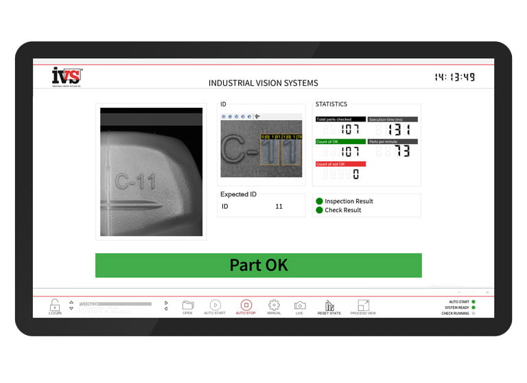
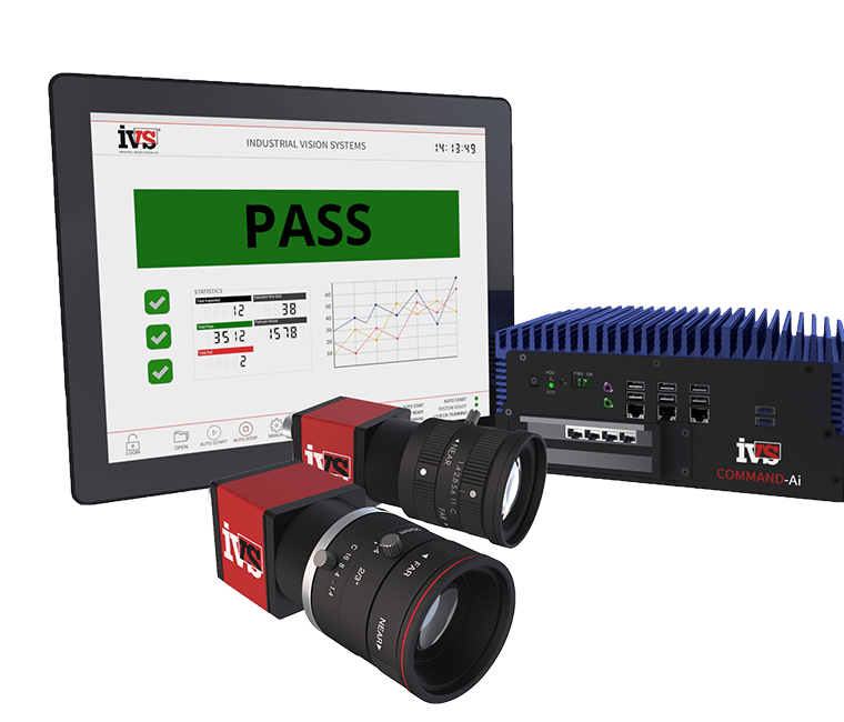
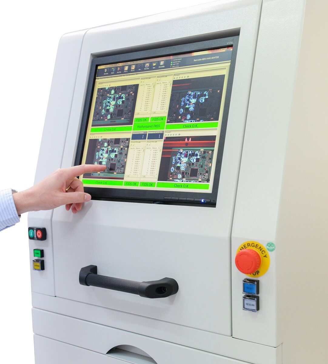
The layout of the operator interface is important to give immediate data and statistical information to the production team. It is important to have an interface that can be easily read from a distance, and displays the necessary information in a single screen. During high-speed inspection operations (such as medical device and pharmaceutical inspection operations) it is not possible to see every product inspected, that’s why a neatly designed vision system display, showing the last failed image, key data and statistical process control (SPC) information provides a ready interface for the operator to drill down on process specifics which may be affecting the quality of the product.

It’s clear why the HMI in quality control vision systems are so crucial to production operations. They help operators see important manufacturing inspection data when necessary, recommend adjustments on the fly, monitor production in real-time and provide useful data about performance all at once.

Top 6 medical device manufacturing defects that a vision system must reject

What does every medical device manufacturer crave? Well, the delivery of the perfect part to their pharmaceutical customer, 100% of the time. One of the major stumbling blocks to that perfect score and getting a Parts Per Million (PPM) rate down to zero are the scratches, cracks and inclusions which can appear (almost randomly) in injection moulded parts. Most of the time, the body in question is a syringe, vial, pen delivery, pipette or injectable product which is transparent or opaque in nature, which means the crack, inclusion, or scratch is even more apparent to the end customer. Here we drill down on the top six defects you can expect to see in your moulded medical device and how vision systems are used to automatically find and reject the failure before it goes out of the factory door.

1. Shorts, flash and incomplete junctions.

Some of the failures are within the tube surface and are due to a moulding fault in production. For example, incomplete injections in mouldings create a noticeable short shot in the plastic ends of the product. The forming of junctions at the bottom end of the tube creates a deformation that must be analysed and rejected. Flash is characterised as additional material which creates an out of tolerance part.

2. Scratches and weld lines

These can be present on the main body, thread area or top shaft. They often have a slight depth to them and can be evident from some angles and less so from others. These could also be confused with weld lines which can run down the shaft or body of a syringe product, but this is also a defect that is not acceptable in production.

3. Cracks

Cracks in a medical device can have severe consequences to the patient and consumer; this could allow the pharmaceutical product to leak from the device, change the dosage or provide an unclean environment for the drug delivery device. Cracks could be in the main body or sometimes in the thread area, or around the sprue.

4. Bubbles, Black Spots and Foreign Materials

Bubbles and black spots are inclusions and foreign material, which are not acceptable on any product, but on a drug delivery device that is opaque or clear in nature, they stand out a lot! These sort of particulates are typically introduced through the moulding process and need to be automatically rejected. Often, the cosmetic nature for these sorts of inclusions is more the issue than the device’s functional ability based on the reject.

5. Sink marks, depressions and distortions

Sink marks, pits, and depressions can cause distortion in the components, thus putting the device out of tolerance or off-specification from the drawing. These again are caused by the moulding process and should be automatically inspected out from the batch.

6. Chips

Chips on the device have a similar appearance to short shots but could be caused on exit from the moulding or via physical damage through movement and storage. Chips on the body can cause out of tolerance parts and potential failure of the device in use.

But how does this automatic inspection work for all the above faults?

Well, a combination of optics, lighting and filters is the trick to identifying all the defects in medical plastic products. This combined with the ability to rotate the product (if it’s cylindrical in nature) or move it in front of many camera stations. Some of the critical lighting techniques used for the automated surface inspection of medical devices are:

Absorbing – the backlight is used to create contrasts of particulates, bubbles and cosmetic defects.
Reflecting – Illumination on-axis to the products creates reflections of fragments, oils and crystallisation.
Scattering – Low angle lighting highlights defects such as cracks and glass fragments.
Polarised – Polarised light highlights fibres and impurities.

These, combined with the use of telecentric optics (an optic with no magnification or perspective distortion), allows the product to be inspected to the extremities, i.e. all the way to the top and to the bottom. Thus, the whole medical device body can be examined in one shot.

100% automated inspection has come a long way in medical device and pharmaceutical manufacturing. Utilising a precision vision system for production is now a prerequisite for all medical device manufacturers.

What are false failures in machine vision (and the art of reducing them.)

Over the last twenty plus years in the machine vision industry we’ve learnt a lot about customer expectation and the need to provide solutions which are robust, traceable and provide good value for money. One of the key elements of any installation or inspection machine is the mystical area of false failures of the vision system, and making sure this is reduced to the point of virtual elimination. A small change in the false failure rate in a positive direction can have a massive impact on yield, especially when the inspection takes place at 500 parts per minute!

For customer’s new to machine vision, it’s a concept they aren’t used to. The idea that you have to have a few false rejects events to happen in order to ensure that no false accepts take place. During the design phase of the vision set-up and inspection routine structure, we review a collection of “Good” parts as well as a pool of “Bad” parts. Statistically, this would imply an infinite number of each in order to calculate the set points for each measured feature. It is impossible to create an effective vision solution without this collection of components. We use various vision software methods to analyse all of the parts and features to create a collection of data sets using these good and bad parts.

This is where the system’s true feasibility will be determined. Once a vision tool has been created for any given feature, a population of data points will usually have some degree of uniqueness across the good and bad parts. If the data does not have two mutually exclusive distributions of results, some good parts must be rejected to ensure that no faulty parts are passed and allowed to continue to the customer. In other words, there is a cost to rejecting some good parts in order to ensure that a failed part is never sent to the customer.

You’ll notice that this chart explains the reasons for false rejections. More importantly, it emphasises that if a system is not rejecting good parts, it may be passing bad ones.

Of course, with all our years of experience in machine vision, we understand this issue – so all our systems and machines are designed so that there is enough difference between good and bad that the distributions are as distinct as possible, that’s the art. That is not so difficult to achieve in presence/absence type applications. It’s more difficult in gauging and metrology vision, where there’s some measurement uncertainty, and extremely difficult in surface flaw detection. Experience in the field of machine vision is everything when it comes to false failure reduction, and that’s what we provide you with our long-standing knowledge in vision systems.

How to run a Gauge R & R study for machine vision

When you’re installing a vision system for a measuring task, don’t be caught out with the provider simply stating that the pixel calibration task is completed by dividing the number of pixels by the measurement value. This does provide a calibrated constant, but it’s not the whole story. There is so much more to precision gauging using machine vision. Measurement Systems Analysis (MSA) and in particular Gauge R&R studies are tests used to determine the accuracy of measurements. They are the de-facto standard in manufacturing quality control and metrology, and especially relevant for machine vision-based checking. Repeated measurements are used to determine variation and bias. Analysis of the measurement results may allow individual components of variation to be quantified. In MSA accuracy is considered to be the combination of trueness (bias) and precision (variation).

The three most crucial requirements of any vision gauging solution are repeatability, accuracy and precision. The variance of repeated measurements, or repeatability, refers to how near the measurements are to each other. The accuracy of the measurements refers to how close they are to the genuine value. The number of digits that can be read from the measurement gauge is known as precision.

A Gauge R & R (also known as Gage R & R) repeatability and reproducibility is defined as the process used to evaluate a gauging instrument’s accuracy by ensuring its measurements are repeatable and reproducible. The process includes taking a series of measurements to certify that the output is the same value as the input, and that the same measurements are obtained under the same operating conditions over a set duration.

The “repeatability” aspect of the GR&R technique is defined as the variation in measurement obtained:

– With one vision measurement system
– When used several times by the same operator
– When measuring an identical characteristic on the same part

The “reproducibility” aspect of the GR&R technique is the variation in the average of measurements made by different operators:

– Who are using the same vision inspection system
– When measuring the identical characteristic on the same part

Operator variation, or reproducibility, is estimated by determining the overall average for each appraiser and then finding the range by subtracting the smallest operator average from the largest.

So, it’s important that vision system measurements are checked against all of these aspects, so a bias test, process capability and gauge validation. The overall study should be performed as per MSA Reference Manual 2010 fourth edition.

More information on IVS gauging and measuring can be found here.

Why using vision systems to capture the cavity ID in injection moulded parts helps you stay ahead of the competition

Machine vision systems are excellent at analysing products, capturing data and providing a large database of useful statistics for your operations and production manager to pore over. For products which are injection moulded we often get tasked with measuring key dimensions, gauging a spout or find the rogue short shot on a medical device. Normally this is at speed, with products running directly out of the Injection Moulding Machine (IMM), up a conveyor and into the vision input (normally a bowl feed, robot or conveyor), with the added bonus of images saved for reference as the automatic inspection takes place. If you’ve had a failure, it’s always a good idea to have the photo of the product to show to the quality team and for process control feedback. Let’s face it, the vision system is a goal keeper, and you need to feedback to the production team to help improve the process.

But what if the failure is intermittent and not always easy to capture? Your quality engineers may be scratching their heads, wondering why there is a product failure every now and then. Is there any way this can be tracked back to source? The neat answer is to complete cavity identification (ID) during the inspection process. The tooling for an IMM can include a cavity number so that each individual product has a unique reference. This is used for other forms of quality feedback, such as reviewing tool wear, tooling failures, short-shot imbalance and general troubleshooting for injection moulded products. So, if the cavity Identification number can be read at speed, saved and the data tracked against it, you start to see a picture of how your process is running, spikes in quality concerns related to a particular cavity, and ultimately full statistical process control of each tool cavity. Utilising precision optical character recognition allows vision systems to read each cavity number (or letter/or combination), to drill down the data to an individual cavity within the tool.

So next time the quality director comes down onto the shop floor asking what cavities are giving you problems, you’ll have all the data to hand (plus the photos to really wow them!).

Why bin picking is one of the most difficult vision system tasks (and how to overcome it!)

Autonomous bin picking, or the robotic selection of objects with random poses from a bin, is one of the most common robotic tasks, but it also poses some of the most difficult technological challenges. To be able to localise each part in a bin, navigate to it without colliding with its environment or other parts, pick it, and safely place it in another location in an aligned position – a robot must be equipped with exceptional vision and robotic intelligence.

Normally the 3D vision system scanner is mounted in a fixed, stationary position in the robotic cell, usually above and in-line with the bin. The scanner must not be moved in relation to the robot after the system has been calibrated. As a general rule of thumb, the more room is required for the bin picking application – including the space for robot movement, the size of the bin and parts, etc. – the larger model of the machine vision scanner required. So more resolution and pixels equates in simple terms to more precision and accuracy.

Calibration is completed with any suitable ball attached to the endpoint of the robotic arm or to the gripper. The ball needs to be made of a material that is appropriate for scanning, which means it needs to be smooth and not too reflective.

One of the problems with this approach is that the 3D vision system itself could cast a shadow on the bin and inhibit a high-quality acquisition of the scene. This problem is usually solved by making a compromise and finding the most optimal position for the scanner in relation to the bin or by manually rearranging the parts within the bin so that the vision system captures them all in the end. But is there another way?

A way to overcome this is to mount the 3D vision system on the robot itself. Of course, there are certain prerequisites to this approach (i.e. the robot can cope with the additional weight, there is room for mounting and there is cycle time available for movement), but there is some functional advantages to this approach.

For a successful calibration, the scanner must be mounted behind the very last joint (e.g. on the gripper). Any changes made to the scanner’s position after the calibration renders the calibration matrix invalid and the whole calibration procedure must be carried out again. This sort of calibration is done with a marker pattern – a flat sheet of paper (or another material) with a special pattern recognized the 3D vision system.

So what are the advantages? Well, you can’t scan your large bin with a smaller (and so lower cost) vision system scanner, because your scanner is mounted above it and its view is fixed. A small scanner mounted directly on the robotic arm allows you to get closer to the bin and choose which part of it to scan, thus potentially saving costs and helping with resolution.

Robotic mounted bin picking may also eradicate the need to darken the room where the robotic cell is located. The ambient light coming from a skylight might pose serious challenges to the deployed 3D vision system. A scanner attached to the robot can make scans of a bin from one side first and then from another, minimising the need to make any unusual adjustments to the environment.

It can also happen that the 3D vision system itself casts shadows on the bin and inhibits a high-quality acquisition of the scene. This problem is usually solved by making a compromise and finding the most optimal position for the scanner in relation to the bin or by manually rearranging the parts within the bin so that the vision system captures them all in the end. Robot mounted picking eliminates this problem as it enables the scanner to “look” at the scene from any angle and from any position.

In conclusion, there are many approaches to automated bin picking using 3D vision systems, each with their own unique approaches dependent on the environment, industrial automation needs, cost and the cycle time available for picking.

Industrial Vision Systems launches optical sorting machines to drive efficiency and minimise waste

Industrial Vision Systems (IVS), a supplier of inspection machines to industry, has launched a range of new optical sorting machines specifically for the high-speed sorting of small components such as fasteners, rings, plastic parts, washers, nuts, munitions and micro components. The devices provide automatic inspection, sorting, grading and classification of products at up to 600 parts per minute. The systems intercept and reject failed parts at high speed, discovering shifts in quality, and providing quality assurance through the production cycle.

The new Optical Sorting Machines from IVS utilise the latest vision inspection algorithms allowing manufacturers to focus on other activities while the fully automated sorting machines root out rogue products and make decisions on quality automatically. For classification checks, the systems use Artificial Intelligence (AI) and Deep Learning, providing the machines with an ability to “learn by example” and improve as more data is captured.

The glass disc of the machine provides 360-degree inspection enabling the system to act as the ‘eyes’ on the factory floor and record production trends and data. By intercepting and rejecting failed parts at high speed, it gives manufacturers the ability to provide 100% automatically inspected product to their customers, without human intervention.

With real-time data and comprehensive reporting to see defect rates, this enables engineers to immediately respond to problems and take corrective action before products are delivered to a customer.

Andrew Waller, director at Industrial Vision Systems, said: “Our machines allow manufacturers to stay ahead of their competitors. These new systems are designed for manufacturers of mass-produced, small products which previously would have struggled to sort quality concerns. We can perceive and detect defects others miss at high-speed. Our optical sorting technology takes vision inspection to the next level. Clear, ultra-high-definition images allow our new generation of systems to recognise even the hardest to spot flaws and to sort wrong batch parts. This allows our customers to achieve continuous yield reductions, categorise failures based on their attributes, and build better products.”

“Innovations in Pharmaceutical Technology” – IVS featured in leading international Pharmaceutical magazine

The articles covers how traditional image processing techniques are being superseded by vision systems utilising deep learning and artificial intelligence in pharmaceutical manufacturing.

Pharmaceutical and medical device manufacturers must be lean, with high-speeds, and an ability to switch product variants quickly and easily, all validated to ‘Good Automated Manufacturing Practice’ (GAMP). Most medical device production processes involve some degree of vision inspection, generally due to either validation requirements or speed constraints (a human operator will not keep up with the speed of production). Therefore, it is critical that these systems are robust, easy-to-understand and seamlessly integrate within the production control and factory information system.

Historically, such vision systems have used traditional machine vision algorithms to complete some everyday tasks: such as device measurement, surface inspection, label reading and component verification. Now, new “deep-learning” algorithms are available to provide an ability for the vision system to “learn”, based on samples shown to the system – thus allowing the quality control process to mirror how an operator learns the process. So, these two systems differ: the traditional system being a descriptive analysis, and the new deep learning systems based on predictive analytics.

Download the magazine from this link (Article Page 30):
https://tinyurl.com/yyj7qvdn

Find more details on IVS solutions for the medical device and pharmaceutical industries here:
https://www.industrialvision.co.uk/vision-systems/vision-sensors/medical-pharma-inspection-solutions

IVS featured in “InVision” magazine in Germany

An article by Christian Demant, Director of IVS, has appeared in the leading German machine vision magazine, “InVision” (www.invision-news.de). The article describes a 3D final inspection industrial automation line for quality control of insulation parts – designed, built and integrated by Industrial Vision Systems. The report covers the major vision inspection elements of the machine process, including:

3D Vision – 3D vision sensors from above and below scan the product, to build up a complete 3D profile of the surface allowing small surface inclusions, dents and raised defects to be automatically assessed and rejected.

All cosmetic and topography is automatically checked.

2D Vision – Precision 2D machine vision cameras from above and below create an accurate measurement profile of the part allowing finite metrology checks on the product. Vision sensors for automated sorting and inspection.

Metal Detection – Automated metal detection allows any rogue metallic parts which could have embedded into the product to be identified.

Check Weigher – The inspection line has to cope with varying sizes of product; the check weigher accurately checks weight allowing over or undersized product to be automatically rejected.
Printing Inspection – Upon passing all inspection processes, the product is automatically marked, and this mark is then automatically inspected by the vision system.

Pick and Place – Good product are picked and stacked, ready for immediate packing by the operator. Reject parts are allowed to run off the outfeed reject zone for reject or rework.

Download the magazine from the following link (Page 46):
https://tinyurl.com/y2oudp5l

Find out more about the machine vision application areas IVS support:
https://www.industrialvision.co.uk/applications

Industrial Vision Systems launches smart Ai vision sensors for high-speed inspection

Industrial Vision Systems (IVS®), a supplier of machine vision systems to industry, has launched the IVS-COMMAND-Ai™ in-line inspection solution designed for high-speed automated visual inspection, helping reduce manufacturer fines and protecting brand reputations. The IVS-COMMAND-Ai Vision Sensors integrate directly with all factory information and control systems, allowing complete part inspection, guidance, tracking and traceability with additional built-in image and data saving.

For those applications requiring complex classification, the IVS-COMMAND-Ai system utilises the latest deep learning artificial intelligence (ai) vision inspection algorithms. New multi-layered “bio-inspired” deep neural networks allow the latest IVS® machine vision solutions to mimic the human brain activity in learning a task, thus allowing vision systems to recognise images, perceive trends and understand subtle changes in images which represent defects.

Designed for complex manufacturing industries such as medical devices, pharmaceuticals, food & drink and automotive, the IVS-COMMAND-Ai Vision Systems are fitted with adaptable HD smart cameras to provide inspection from all angles and at high precision. This allows production lines to review and alert any flaws and defects in real-time, providing instant factory information on compatible devices. It also possesses speeds of up to 60 frames per second and can quickly be integrated on-line to inspect high speed and static products.

By achieving a robust inspection performance, the new IVS-COMMAND-Ai Vision Systems oversees complex vision inspections such as presence verification, OCR and gauging through to surface, defect and quality inspection in one solution. Comprehensive Statistical Process Control (SPC) data also provides closed-loop control to further safeguard production.

All IVS vision sensors can be integrated onto production lines, assembly cells, workbenches, robots and linear slides. Their robust design allows vision sensor integration into any industrial production process for seamless inspection, identification or guidance.

Earl Yardley, director at Industrial Vision Systems, comments: “Our vision systems are very easy to program, are highly accurate, offer easy maintenance and provide peace of mind in final quality acceptance. However, the IVS-COMMAND-Ai vision systems take it a step further. It is the complete, robust quality control inspection vision sensor solution, and it is ready to be deployed in all manufacturing environments. It will improve yield and deliver immediate improvements to product quality; and at these critical times, reliability and consistency are vital.”

Vision Sensors

Deep Learning (AI) – Enhancing automated inspection of medical devices?

Integrated quality inspection processes continue to make a significant contribution to medical device manufacturing production, including the provision of automated inspection capabilities as part of real-time quality control procedures. Long before COVID-19, medical device manufacturers were rapidly transforming their factory floors by leveraging technologies such as Artificial Intelligence (AI), machine vision, robotics, and deep learning.

These investments have enabled them to continue to produce critical and high-demand products during these current times, even ramping up production to help address the pandemic. Medical device manufacturers must be lean, with high-speeds, and an ability to switch product variants quickly and easily, all validated to ‘Good Automated Manufacturing Practice’ (GAMP). Most medical device production processes involve some degree of vision inspection, generally due to either validation requirements or speed constraints (a human operator will not keep up with the speed of production). Therefore, it is critical that these systems are robust, easy-to-understand and seamlessly integrate within the production control and factory information system.

Deep learning

Historically, such vision systems have used traditional machine vision algorithms to complete some everyday tasks: such as device measurement, surface inspection, label reading and component verification. Now, new “deep-learning” algorithms are available to provide an ability for the vision system to “learn”, based on samples shown to the system – thus allowing the quality control process to mirror how an operator learns the process. So, these two systems differ: the traditional system being a descriptive analysis, and the new deep learning systems based on predictive analytics.
Innovative machine and deep learning processes ensure more robust recognition rates. Medical device manufacturers can benefit from enhanced levels of automation. Deep learning algorithms use classifiers, allowing image classification, object detection and segmentation at a higher speed. It also results in greater productivity, reliable identification, allocation, and handling of a broader range of objects such as blister packs, moulds and seals. By enhancing the quality and precision of deployed machine vision systems, this adds a welcome layer of reassurance for manufacturers operating within this in-demand space.
Deep learning has other uses in medical device manufacturing too. As AI relies on a variety of methods, including machine learning and deep learning, to observe patterns found in data, deep learning is a subfield of machine learning that mimics the neural networks in the human brain by creating an artificial neural network (ANN). Like the human brain solving a problem, the software takes inputs, processes them, and generates an output. Not only can it help identify defects, but it can, as an example, help identify missing components from a medical set. Additionally, deep learning can often classify the type of defect, enabling closed-loop process control.
Deep learning can undoubtedly improve quality control in the medical device industry by providing consistent results across lines, shifts, and factories. It can reduce labour costs through high-speed automated inspection. It can help manufacturers avoid costly recalls and resolve product issues, ultimately protecting the health and safety of those towards the end of the chain.

AI Limitations

However, deep learning is not a silver bullet for all medical device and pharmaceutical vision inspection applications. It may be challenging to adopt in some applications due to the Federal Drugs Administration (FDA)/GAMP rules relating to validation.

The main issue is the limited ability to validate such systems. As the vision inspection solution utilising AI algorithms needs sample data, both good and bad samples – it makes validating the process extremely difficult, where quantitative data is required. Traditional machine vision will provide specific outputs relating to measurements, grey levels, feature extraction, counts etc. which are generally used for validating a process. With deep learning, the only output is “pass” or “fail”.

This is a limiting capability of deep learning enabled machine vision solutions – the user has to accept the decision provided by the AI tool blindly, providing no detailed explanation for the choice. In this context, the vision inspection application should be reviewed in advance, to see if AI is applicable and appropriate for such a solution.

Conclusion

In conclusion, deep-learning for machine vision in industrial quality control is now widely available. Nevertheless, each application must be reviewed in detail – to understand if the most appropriate solution is to utilise traditional machine vision with quantifiable metrics or the use of deep-learning with its decision based on the data pool provided. As AI and deep learning systems continue to develop for vision system applications, we will see more novel ways of adapting the solutions to replace traditional image processing techniques.

You can find out more details on IVS deep learning vision systems here:
https://www.industrialvision.co.uk/applications/deep-learning-artificial-intelligence-ai

Industrial Vision Systems launches free ‘Vision To Automate’ guide

Industrial Vision Systems (IVS), a supplier of machine vision systems to industry, has today launched a free downloadable guide explaining and reviewing vision systems and machine vision. The new ‘Vision to Automate’ guide is designed to support and direct UK manufacturers who are looking to adopt smart factory systems such as robotics, vision systems, automation, and machine learning.

With manufacturers desperately keen to resume some normality when it comes to production post-COVID-19, this 32-page premium guide reviews the basics of machine vision and vision systems, including components, applications and return on investment. ‘Vision to Automate’ also drills down into how an automated factory floor can increase productivity by improving processes, provide greater flexibility, and increase the volume of parts. This, in turn, reduces costs through a reduction in re-testing and labour.

IVS is already witnessing an increasing number of factory floor managers looking to increase the number of collaborative robots operating side by side with human workers post-lockdown, to ease fears of picking up infections. ‘Vision to Automate’ explains how this crucial human-robot collaboration will support the flexible production of highly complex items in lower quantities.

The guide also dissects automated bin-picking robots, which allows vision and robotics to operate autonomously picking product from bins and totes to load machines, bag products or to produce sub-assemblies. This is an area which IVS believes will become common across factory floors as workplaces evolve post-lockdown.

Earl Yardley, director at Industrial Vision Systems, comments: “The key for us is to outline the basics. What is machine vision? How does it work? What can it be used for? ‘Vision to Automate’ answers those questions. Forward-thinking businesses are leveraging automation to support their organisation, and I believe we will continue to see critical changes to working practices and automation deployment. This will create new opportunities across manufacturing within many industry sectors. This includes cutting edge production ideologies with vision robotics and an increasing ability to reduce human to human contact with the deployment of autonomous robotics. We see a growing demand for vision-guided robot systems to maintain production capacity and reduce dependence on the human workforce which will further drive the adoption of flexible manufacturing for generations to come. Removing operators from some production operations will allow factories to reopen with reduced human to human contact, increasing yield and protecting the rest of what is likely to be an anxious workforce.”

Download for FREE via the IVS homepage.
www.industrialvision.co.uk